 |

 IBM-AUSTRIA - PC-HW-Support 30 Aug 1999
 |
System Board (TP 240 - 2609)
System Board
Note: See 'Replacing the System Board' before proceeding.
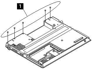
- Remove the screws as shown.

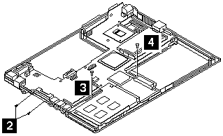
- Turn the notebook over, remove the two screws from the FDD connector.

- Remove the screw from the PCMCIA slot.
- Remove the battery terminal screw.
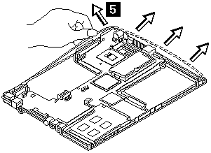
- Gripping firmly as shown, separate the base cover around the sides from the system board.

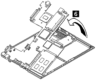
- Remove the system board from the base cover Asm.

| Step |
Size (Quantity) |
Head & Color |
Torque |
| 1 |
M2.0 x 4 (5) |
Flat head, black |
2.5 kgf-cm |
| 2 |
M2.0 x 6 (2) |
Flat head, black |
2.0 kgf-cm |
| 3 |
M2.0 x 4 (1) |
Flat head, black |
2.0 kgf-cm |
| 4 |
M2.0 x 8 (1) |
Flat head, black |
2.0 kgf-cm |
Note: Make sure you use the correct screw for replacement.
Back to 
More INFORMATION / HELP is available at the IBM-HelpCenter
Please see the LEGAL - Trademark notice.
Feel free - send a  for any BUG on this page found - Thank you.


 for any BUG on this page found - Thank you.