Back to Contents Page

System Board

Dell™ Latitude™ X200 Service Manual


Removing the System Board

NOTICE: Disconnect the computer and any attached devices from electrical outlets.
NOTICE: To avoid ESD, ground yourself by using a wrist grounding strap or by touching an unpainted metal surface on the computer.
NOTICE: Read "Preparing to Work Inside the Computer" before performing the following procedure.
  1. Remove the battery.

  2. Remove the keyboard.

  3. Remove the palm rest.

  4. Remove the hinge covers.

  5. Remove the display assembly.

  6. Remove the keyboard tray.

  7. Remove the hard drive.

  8. Remove the memory module.

  9. Remove the Mini PCI card, if present.

  10. Remove the four M2 x 4-mm screws that secure the system board to the bottom case.

NOTE: Each system board screw has an arrow beside it.
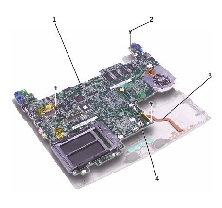
1

system board

2

M2 x 4-mm screws (4)

3

status light (LED) cable

4

ZIF connector

  1. Disconnect the left and right speakers from their system board connectors.

  2. Disconnect the reserve battery connector from the system board connector.

  3. Lift the ZIF connector, and remove the status light (LED) cable from its ZIF connector on the system board.

  4. Lift the system board up and out of the bottom case.

  5. Remove the modem daughter card, and set it aside to install in the replacement system board.

Replacing the System Board

  1. Install the modem daughter card that you removed from the old system board in the replacement system board.

  2. Place the system board in the bottom case.

NOTE: Route cables so that they will not be crimped or pinched when the complete assembly is put back together.
  1. Reconnect the status light (LED) cable to the system board ZIF connector.

  2. Reinstall the four M2 x 4-mm screws that secure the system board to the bottom case.

NOTE: After replacing the system board, enter the computer service tag sequence into the BIOS of the replacement system board.

Back to Contents Page