Back to Contents Page

Keyboard

Dell™ Latitude™ X200 Service Manual


Removing the Keyboard

NOTICE: Disconnect the computer and any attached devices from electrical outlets.
NOTICE: To avoid ESD, ground yourself by using a wrist grounding strap or by touching an unpainted metal surface on the computer.
NOTICE: Read "Preparing to Work Inside the Computer" before performing the following procedure.
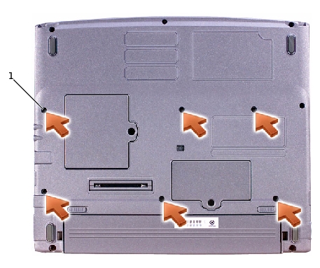
  1. Remove the battery.

  2. Remove the six M2 x 4-mm screws labeled with an arrow (one of the six screws is labeled "K" with an arrow) from the bottom of the computer.

1

M2 x 4-mm screws (6)

NOTICE: The keycaps on the keyboard are fragile, easily dislodged, and time- consuming to replace. Be careful when removing and handling the keyboard.
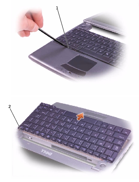
  1. Turn the computer over, and insert a ¼-inch flat-blade screwdriver into the slot to the right of the keyboard locator tab.

1

keyboard locator tab

2

keyboard securing tabs (4)

  1. Pry up the keyboard locator tab, and the keyboard pops up.

  2. Pull the keyboard a small distance toward the front of the computer to release the four securing tabs located across the back edge of the keyboard.

  3. Rotate the keyboard toward the front of the computer and place it face-down on the palm rest.

NOTICE: Do not pull on the keyboard flex cable.
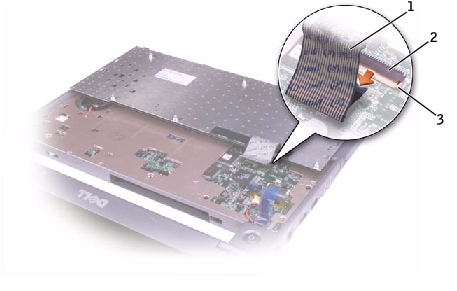
  1. Open the ZIF connector on the system board by pulling the ZIF connector tabs toward the back of the computer.

1

keyboard flex cable

2

ZIF connector

3

ZIF connector tabs (2)

  1. Remove the keyboard flex cable from the ZIF connector.

  2. Lift the keyboard up and out of the computer.

Replacing the Keyboard

  1. Place the keyboard face-down on the palm rest, with the keyboard flex cable pointing toward the back of the computer.

NOTICE: To avoid damage to the connector pins, insert the keyboard flex cable evenly into the ZIF connector on the system board, and do not reverse the keyboard flex cable.
  1. Ensure that the ZIF connector is open by pulling the ZIF connector tabs toward the back of the computer.

  2. Press the keyboard flex cable into the ZIF connector.

  3. Close the ZIF connector by pushing the ZIF connector tabs toward the front of the computer.

To aid with proper flex cable connection, a blue locator line has been added near the end of the flex cable. Press the cable into the connector until the blue line disappears and hold the cable steady while you close the ZIF connector. (The blue line may reappear after the connector is closed, which should not indicate a problem with the connection.)

NOTICE: Position the keyboard flex cable so that it is not pinched when you replace the keyboard in the bottom case.
  1. Rotate the keyboard back and fit it into the bottom case.

  2. Ensure that all four keyboard securing tabs are engaged in their respective slots before trying to completely seat the keyboard. Press down on the left and right keys to help control tab/slot alignment.

When the keyboard appears to be completely seated, confirm that the front edge of the keyboard is aligned with the edge of the palm rest before proceeding.

  1. Replace the six M2 x 4-mm screws on the bottom of the computer.


Back to Contents Page