 Memory Module
Dell™ Latitude™ X200 Service Manual
 |
NOTICE: Disconnect the computer and any attached devices from electrical outlets, and remove any installed batteries. |
|
NOTICE: To avoid ESD, ground yourself by using a wrist grounding strap or by touching an unpainted metal surface on the computer. |
|
NOTICE: Read "Preparing to Work Inside the Computer" before performing the following procedure. |
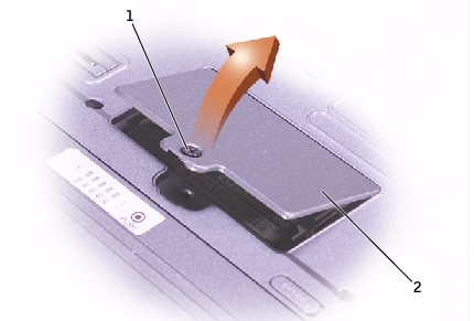
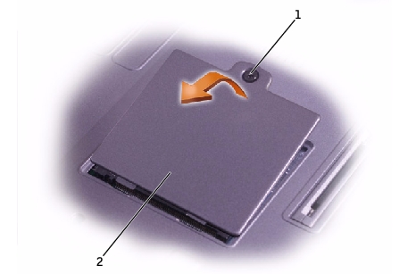
1 |
captive screw |
2 |
memory module cover |
|
NOTICE: To prevent damage to the memory module connector, do not use tools to spread the inner metal tabs that secure the memory module. |
|
NOTICE: Handle memory modules by their edges, and do not touch the components on a module. |
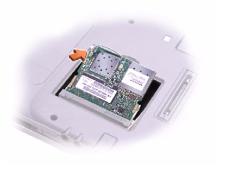
The module should pop up.
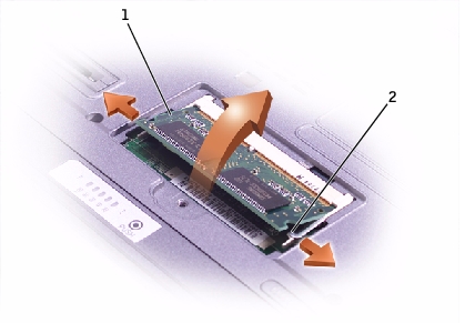
1 |
memory module |
2 |
securing clips (2) |
 |
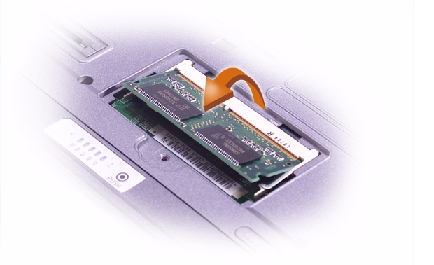
NOTE: If the memory module is not installed properly, the computer does not boot. No error message indicates this failure. |
|
NOTICE: If the memory module cover is difficult to close, remove the module and reinstall it. Forcing the cover to close may damage your computer. |
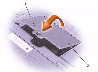
1 |
captive screw |
2 |
memory module cover |
As the computer boots, it detects the additional memory and automatically updates the system configuration information.
|
NOTICE: Disconnect the computer and any attached devices from electrical outlets, and remove any installed batteries. |
|
NOTICE: To avoid ESD, ground yourself by using a wrist grounding strap or by touching an unpainted metal surface on the computer. |
|
NOTICE: Read "Preparing to Work Inside the Computer" before performing the following procedure. |
1 |
captive screw |
2 |
Mini PCI card cover |
|
NOTICE: The connectors are keyed for correct insertion; do not force the connections. |