Back to Contents Page
Dell™ Latitude™ C640
Service Manual
The system board's BIOS chip contains the service tag sequence, which is also visible on a bar code label on the bottom of the computer. The replacement kit for the system board includes a CD that provides a utility for transferring the service tag sequence to the replacement system board.
 |
NOTICE: Disconnect the computer and any attached devices from electrical
outlets, and remove any installed batteries.
|
|
NOTICE: To avoid ESD, ground yourself by using a wrist grounding strap or
by touching an unpainted metal surface on the computer.
|
- Remove the hard drive.
- Remove the keyboard.
- Remove the display assembly.
- Remove the palm rest.
- Remove the microprocessor thermal cooling assembly.
- Remove the microprocessor module.
- Remove the modem, memory modules, and Mini PCI card.
- From the bottom of the computer, remove the six M2.5 x 5-mm screws
labeled "circle B" that secure the system board to the bottom case.
- Remove the three M2.5 x 5-mm screws labeled "circle B" that secure
the fan guard to the bottom case.
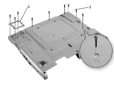
1 |
fan guard |
2 |
M2.5 x 5-mm screws (9) |
- Turn the computer over and remove the M2.5 x 5-mm screw, which is
labeled "circle B" with an arrow on the front center of the system board
by the battery connector.
1 |
M2.5 x. 5-mm screw (1) |
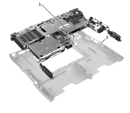
2 |
audio connector locations; pull outward here |
- Remove the speaker assemblies from the bottom case.
- Pull the right side of the bottom case, next to the audio connectors,
away from the system board as you simultaneously lift the front of the
system board out and away from the bottom case.
- Install the microprocessor module on the replacement system board.
- Install the replacement system board:
- Insert the external microphone and headphone connectors
through the bottom case.
- Replace the six M2.5 x 5-mm screws, starting on the right side of
the bottom case.
- Replace the fan guard, inserting the tab into the bottom case, and
replace the three M2.5 x 5-mm screws. Replacing the screw
opposite the tab first makes it easier to insert and replace the other
two screws.
- Replace the modem and the microprocessor thermal cooling assembly
that you removed from the old system board.
 |
NOTE: Route cables so that they will not be crimped or pinched when the
complete assembly is put back together.
|
- Install the right and left speaker assemblies that came with the new
system board in the bottom case.
- Replace the palm rest, the keyboard, the display assembly, and the hard
drive.
- Replace the module bay devices and any PC Cards or plastic blanks in
the PC Card slot.
- Insert the flash BIOS update floppy disk or CD that accompanied the
replacement system board, and turn on the computer. Follow the
instructions on the screen.
|
NOTE: After replacing the system board, enter the computer service tag
sequence into the BIOS of the replacement system board.
|
Back to Contents Page