Back to Contents Page

Keyboard

Dell™ Latitude™ C640 Service Manual


Removing the Keyboard

NOTICE: Disconnect the computer and any attached devices from electrical outlets, and remove any installed batteries.
NOTICE: To avoid ESD, ground yourself by using a wrist grounding strap or by touching an unpainted metal surface on the computer.
NOTICE: Read "Preparing to Work Inside the Computer" before performing the following procedure.
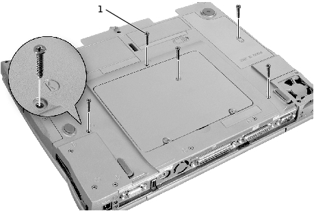
  1. Remove the hard drive.

  2. Turn the computer over, and remove the five M2.5 x 12-mm screws labeled "circle K."

1

M2.5 x 12-mm screws (5)

  1. Turn the computer over and open the display.

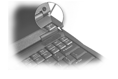
NOTICE: The keycaps on the keyboard are fragile, easily dislodged, and time- consuming to replace. Be careful when removing and handling the keyboard.
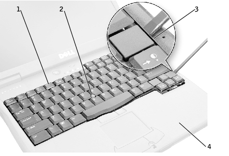
  1. Remove the center control cover:

    1. Insert a small, flat-blade screwdriver or plastic scribe into the notch at the right end of the center control cover and pry up the cover.

    1. Lift the center control cover up and away from the bottom case.

  1. To release the keyboard from the palm rest, use a small, flat-blade screwdriver or plastic scribe to pry up the right edge of the keyboard near the blank key.

1

keyboard

2

track stick

3

blank key

4

palm rest                      

  1. Lift the keyboard straight up about an inch and then rotate it forward toward the front of the computer, until the key face is resting on the palm rest.

NOTICE: Do not pull on the keyboard flex and track stick cables.
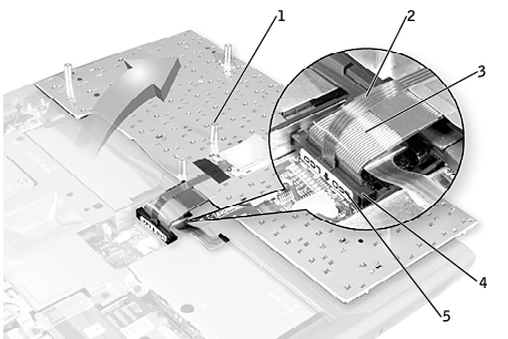
  1. Pull up on the keyboard connector to disconnect it from the keyboard interface connector on the system board.

1

boss supports (5)

2

track stick cable

3

keyboard flex cable

4

keyboard interface connector

5

orientation label

  1. Remove the keyboard from the bottom case.

Replacing the Keyboard

  1. Place the keyboard on the palm rest at the front of the computer with the keys face down and the connector toward the back of the computer.

NOTICE: To avoid damage to the connector pins, press the keyboard connector evenly into the interface connector on the system board, and do not reverse the keyboard connector.
  1. Connect the keyboard connector to the interface connector on the system board.

The keyboard connector may have a label showing the correct orientation of the keyboard connector (relative to the display) in the system-board interface connector.

  1. Carefully turn the keyboard over. Align the keyboard boss supports, fit the left side of the keyboard into place, and then snap the right side of the keyboard into place.

NOTICE: Position the keyboard flex and track stick cables so that they are not pinched when you replace the keyboard in the bottom case.
  1. Check that the keyboard is correctly installed. The keys should be flush with the left and right surfaces of the palm rest.

  2. Replace the center control cover, close the display assembly, and then turn the computer over.

  3. Reinstall the five M2.5 x 12-mm screws in the holes labeled "circle K."


Back to Contents Page