 Memory Modules
Dell™ Latitude™ C640 Service Manual
 |
NOTICE: Disconnect the computer and any attached devices from electrical outlets, and remove any installed batteries. |
|
NOTICE: To avoid ESD, ground yourself by using a wrist grounding strap or by touching an unpainted metal surface on the computer. |
|
NOTICE: Read "Preparing to Work Inside the Computer" before performing the following procedure. |
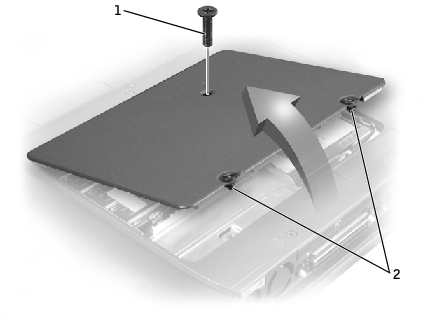
1 |
M2.5 x 12-mm screw (1) |
2 |
captive screws (2) |
|
NOTICE: Disconnect the computer and any attached devices from electrical outlets, and remove any installed batteries. |
|
NOTICE: To avoid ESD, ground yourself by using a wrist grounding strap or by touching an unpainted metal surface on the computer. |
|
NOTICE: Read "Preparing to Work Inside the Computer" before performing the following procedure. |
|
NOTICE: To prevent damage to the memory module connector, do not use tools to spread the inner metal tabs that secure the memory module. |
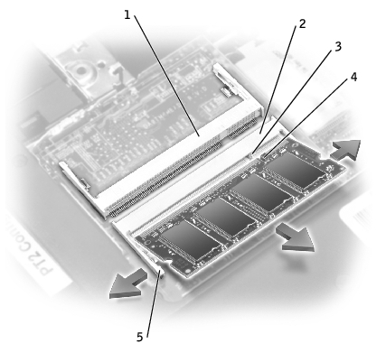
1 |
JDIM 2 memory socket |
2 |
JDIM 1 memory socket |
3 |
keying tab |
4 |
keying notch |
5 |
inner tabs (2 per socket) |
 |
NOTE: Memory modules are keyed, or designed to fit into their sockets, in only one direction. |
|
NOTICE: The memory module must be inserted at a 45-degree angle to avoid damaging the connector. |
You must remove the Mini PCI card before the system board can be removed.
|
NOTICE: Disconnect the computer and any attached devices from electrical outlets, and remove any installed batteries. |
|
NOTICE: To avoid ESD, ground yourself by using a wrist grounding strap or by touching an unpainted metal surface on the computer. |
|
NOTICE: Read "Preparing to Work Inside the Computer" before performing the following procedure. |
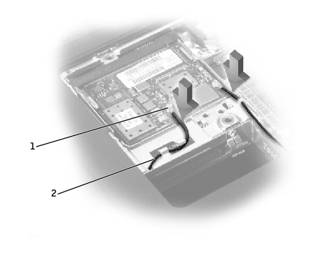
1 |
antenna connectors on card (2) |
2 |
antenna cables (2) |
|
NOTICE: The connectors are keyed for correct insertion; do not force the connections. |
|
NOTICE: Disconnect the computer and any attached devices from electrical outlets, and remove any installed batteries. |
|
NOTICE: To avoid ESD, ground yourself by using a wrist grounding strap or by touching an unpainted metal surface on the computer. |
|
NOTICE: Read "Preparing to Work Inside the Computer" before performing the following procedure. |
|
NOTICE: Do not pull on the modem cable. Pull from the modem connector to disconnect the cable. |
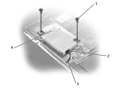
1 |
M2 x 3-mm screws (2) |
2 |
modem connector |
3 |
modem cable |
4 |
pull-tab |
|
NOTICE: The connectors are keyed for correct insertion; do not force the connections. |
|
NOTICE: Pressing down on the modem somewhere other than on the pull-tab can break the modem. |