Preparing to Work Inside the Computer
Dell™ Latitude™ C640 Service Manual
Preparing to Work Inside the Computer

|
CAUTION: Before working inside your computer, read the safety instructions in your System Information Guide. |
|
|
CAUTION: Only a certified service technician should perform repairs on your computer. Damage due to servicing that is not authorized by Dell is not covered by your warranty. |
 |
NOTICE: To avoid damaging the computer, perform the following steps before you begin working inside the computer. |
 |
NOTE: Before turning off the computer, ensure that the computer is not in a power management mode. If you cannot shut down the computer using the computer operating system, press and hold the power button for 4 seconds. |
|
NOTICE: To avoid damaging the system board, you must remove the main battery and secondary battery (if present) before you service the computer. |
The procedures in this manual require the following tools:
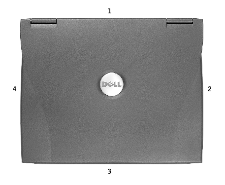
1 |
back |
2 |
right |
3 |
front |
4 |
left |
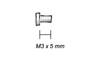
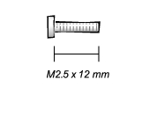
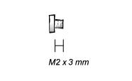
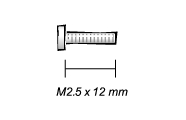
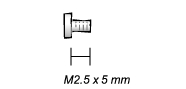
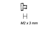
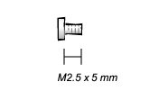
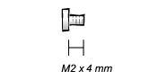
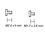
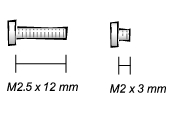
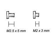
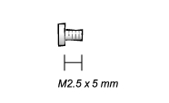
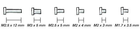
When you are removing and replacing components, photocopy the placemat as a tool to lay out and keep track of the screws. The placemat provides the number of screws and their sizes.
|
NOTICE: When reinstalling a screw, you must use a screw of the correct diameter and length. Ensure that the screw is properly aligned with its corresponding hole, and avoid overtightening. |
Hard Drive Door: (1 each)
|
Memory Module Cover: (2 captive screws) (1 each) NOTE: The single screw is one of the five keyboard screws.
|
Modem to (2 each)
|
Keyboard to (5 each)
|
Hinges to Bottom Case: (5 each)
|
Display-Feed Flex Cable: (4 each)
|
Display Bezel: (6 each)
Rubber Screw Covers (6 each) |
Display Panel to Top Cover: (5 each)
|
Display Latch: (2 each) (2 each)
|
Palm Rest to (3 each) (5 each)
|
Hybrid Cooling Fan: (2 each) (1 each)
|
System Board to Bottom Case: (10 each)
|