|| Diagnostic Tools || Help Desk || Contribute || About || Contact || Home ||
|
|
|
|| Database Index
|| Find Manuals
|| Bios info
|| Manufacturers
|| Testing Tips || || Diagnostic Tools || Help Desk || Contribute || About || Contact || Home || |

|
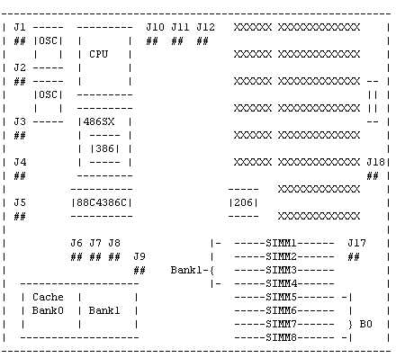
4386c ISA Motherboard
Solution - 4386C

Specification
=============

Processor: 80386DX/80486SX/80486DX
Memory Capacity: up to 32MB
Mem. Configuration: 1/2/4/8/16/32 MB
Memory using: 256K/1M/4M Module, memory up to 32MB on board, 30pin modules
BIOS Type: AMI ROM BIOS
Slots: six 16bit and two 8bit
form factor: 2/3 baby AT size
board design: four layer implementation
misc connectors: reset button, turbo switch, external batt.


SIMM Installation
=================

Bank0 alone or Bank0 and Bank1 exactly the same (256K,1M,4M).


Cache SRAM Install Selection
============================

J6   J7   J8   J9    CacheB0      CacheB1      tag   size
---------------------------------------------------------
2-3  2-3  2-3  open   8KX8, 4pcs   none        8KX8  32K
2-3  1-2  2-3  open   8KX8, 4pcs   8KX8, 4pcs  8KX8  64K
1-2  1-2  2-3  open  32KX8, 4pcs   none        8KX8 128K
1-2  1-2  1-2  short 32KX8, 4pcs  32KX8, 4pcs 32KX8 256K


CPU TYPE CHOICE
===============

J10    J11    J12    using
---------------------------------------
short  2-3    1-2    486DX, 486DX2, P24
short  1-2    1-2    486SX, P23T
open   open   2-3    486SX


MISC JUMPERS
============

J17: Display adapter setup
open = mono
close = color

J1: Keylock & Power Led Connector
pin 1 = LED power
pin 2 = not used
pin 3 = ground
pin 4 = keyboard inhibiter
pin 5 = ground

J2: Speaker connector
pin 1 = data out
pin 2 = not used
pin 3 = ground
pin 4 = +5V

J3: Reset SW Connector
pin 1 = ground
pin 2 = reset in

J4: Turbo LED Connector
pin 1 = - cathode
pin 2 = + anode

J5: Turbo SW Connector
pin 1 = ground
pin 2 = select pin

J18: External Battery Connector
pin 1 = battery (+)
pin 2,3 = short is internal battery 3.6V used
pin 4 = ground

( J18: 1-2 normal operation (default)
       3-4 clear CMOS memory (206 setup of data) )
|