|
|

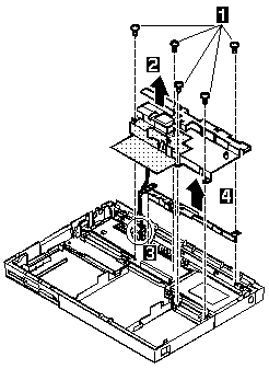
NOTE: The shaded part in the figure is attached to the speaker shield assembly with light adhesive. This is a separate FRU from the speaker shield assembly.
3 When raising the speaker shield assembly,
make sure that the shield assembly does not hook
the three flexible cables of the keyboard.
For Model 360, gently raise the speaker
shield assembly to avoid damaging the speaker cable.
(For Models 355 and 355Cs, skip step 3, the speaker
cable has already been removed.)
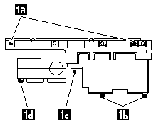
Use the following table for reference when replacing parts.
| Step | Location (Quantity) | Length |
|---|---|---|
| 1a | Speaker shield (1) | 4 mm |
| 1b | Hard disk drive connector (2) | 6 mm |
| 1c | System board (1) | 16 mm |
| 1d | System board, spacer (1) | 16 mm |
NOTE: Make sure you use the correct screw. Screw Size Chart
Please see the LEGAL - Trademark notice.
Feel free - send a  for any BUG on this page found - Thank you.