Back to Contents Page

Battery and Module Bay Latches

Dell™ Latitude™ C640 Service Manual


Removing the Battery and Module Bay Latches

NOTICE: Disconnect the computer and any attached devices from electrical outlets, and remove any installed batteries.
NOTICE: To avoid ESD, ground yourself by using a wrist grounding strap or by touching an unpainted metal surface on the computer.
NOTICE: Read "Preparing to Work Inside the Computer" before performing the following procedure.
  1. Remove the hard drive.

  2. Remove the keyboard.

  3. Remove the display assembly.

  4. Remove the palm rest.

  5. To remove the latch release button, use a plastic scribe to push inward on the snap tabs in the upper latch assembly until the latch release button is released from the bottom case.

To prevent the upper latch assembly from coming loose, apply pressure to the latch and spring while removing the latch release button.
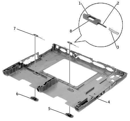
  1. If you are also removing the upper latch assembly, lift it out of the latch holding fixture.

1

bumps (2 per latch)

5

latch release buttons (2)

2

slider

6

snap tabs (2 per latch assembly)

3

spring

7

upper latch assemblies (2)

4

bottom case

8

wear rib

Replacing the Battery and Module Bay Latches

  1. If you are replacing the upper latch assembly:

    1. Slide the spring onto the slider, and install the upper latch assembly in the holding feature on the inside of the bottom case.

    1. Ensure that the slider is inserted into the hole, that the side of the latch with the two bumps is facing the back of the case, and that the side with the wear rib is facing the front of the case.

NOTE: The latch will not function properly if the slider is oriented incorrectly.
  1. Hold down the upper latch assembly and snap in the new latch release button through the bottom case, ensuring that the snap tabs are fully engaged in the upper latch assembly.

  2. Ensure that the newly installed latch release button moves smoothly and freely when pushed and released.


Back to Contents Page