 Memory Module
Dell™ Inspiron™ 8500 Service Manual

|
CAUTION: Before working inside your Dell™ computer, read the safety instructions in your Owner's Manual. |
|
|
CAUTION: To prevent static damage to components inside your computer, discharge static electricity from your body before you touch any of your computer's electronic components. You can do so by touching an unpainted metal surface. |
 |
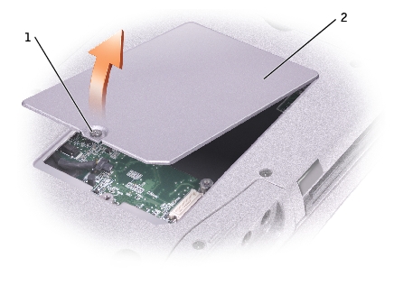
NOTE: Memory modules purchased from Dell are covered under your computer warranty. |
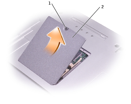
1 |
|
2 |
 |
NOTICE: To prevent damage to the memory module connector, do not use tools to spread the inner metal tabs that secure the memory module. |
|
NOTICE: Handle memory modules by their edges, and do not touch the components on a module. |
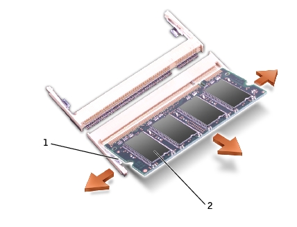
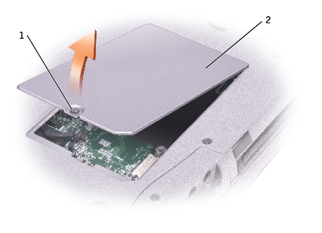
1 |
|
2 |
|
NOTICE: If you need to install memory modules in two connectors, install a memory module in the connector labeled "DIMMA (Slot 1)" before you install a module in the connector labeled "DIMMB." |
|
NOTE: If the memory module is not installed properly, the computer does not boot. The Num Lock and Scroll Lock lights blink about ten times. |
|
NOTICE: If the memory module cover is difficult to close, remove the module and reinstall it. Forcing the cover to close may damage your computer. |
As the computer boots, it detects the additional memory and automatically updates the system configuration information.
If you ordered a Mini PCI card at the same time that you ordered your computer, Dell has already installed the card for you.
|
|
CAUTION: Before working inside your computer, read the safety instructions in your Owner's Manual. |
|
|
CAUTION: To prevent static damage to components inside your computer, discharge static electricity from your body before you touch any of your computer's electronic components. You can do so by touching an unpainted metal surface. |
|
NOTICE: Handle components and cards by their edges, and avoid touching pins and contacts. |
1 |
|
2 |
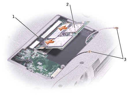
1 |
|
2 |
|
3 |
|
NOTICE: To avoid damaging the Mini PCI card, never place cables on top of or under the card. |
|
NOTICE: The connectors are keyed to ensure correct insertion. If you feel resistance, check the connectors and realign the card. |

1 |
|
2 |
|
|
CAUTION: Before working inside your computer, read the safety instructions in your Owner's Manual. |
|
|
CAUTION: To prevent static damage to components inside your computer, discharge static electricity from your body before you touch any of your computer's electronic components. You can do so by touching an unpainted metal surface. |
|
NOTICE: Handle components and cards by their edges, and avoid touching pins and contacts. |
1 |
|
2 |

1 |
|
2 |
|
3 |
|
4 |
|
5 |
|
NOTICE: The cable connectors are keyed for correct insertion; do not force the connections. |
|
NOTICE: To prevent damage to the modem, press the modem into the connector directly over the connector. |
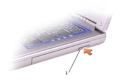
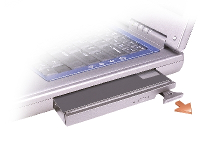
Your computer ships with an optical drive installed in the module bay. However, the device screw is not installed in the optical drive but packaged separately. When you install your device in the module bay, you can install the device screw.
|
NOTE: You do not need to install the device screw unless you want to secure the module inside the computer for security purposes. |
|
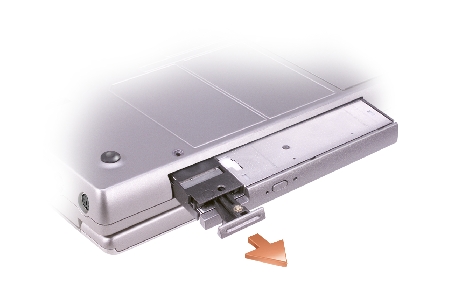
NOTICE: To prevent damage to devices, place them in a safe, dry place when they are not installed in the computer. Avoid pressing down on them or placing heavy objects on top of them. |
1 |
|
NOTICE: To prevent damage to devices, place them in a safe, dry place when they are not installed in the computer. Avoid pressing down on them or placing heavy objects on top of them. |

1 |
|
NOTICE: Insert devices into the module bay before you dock and turn on the computer. |