DIAMOND FLOWER INC.
MIO-400KF REV. F
|
|
Data bus: 16-bit, ISA
Size: Half-length, full-height card
Hard drives supported: Two IDE (AT) Interface drives
Floppy drives supported: Two 360KB, 720KB, 1.2MB, or 1.44MB drives
|
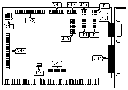
CABLE CONNECTIONS | |
|
4-pin connector-drive active LED |
CN1 |
|
34-pin data cable connector-floppy drive |
CN2 |
|
16-pin connector-game port |
CN3 |
|
10-pin connector-serial port 2 |
CN4 |
|
40-pin AT Interface (IDE) connector-internal |
CN5 |
|
DB-9 male connector-serial port 1 |
CN6 |
|
DB-25 female connector-parallel port |
CN7 |
|
USER CONFIGURABLE SETTINGS | |||
|
Function |
Location |
Setting | |
| » |
Hard drive enabled |
JP3/jumper 8 |
pins 2 & 3 closed |
|
Hard drive disabled |
JP3/jumper 8 |
pins 1 & 2 closed | |
| » |
Game port enabled |
JP3/jumper 9 |
pins 2 & 3 closed |
|
Game port disabled |
JP3/jumper 9 |
pins 1 & 2 closed | |
|
SERIAL PORT SIGNAL STATUS JP1 - SERIAL PORT 1 - JP2 - SERIAL PORT 2 | |||
|
Function |
Location |
Setting | |
| » |
DCD (Data Carrier Detect) - NORMAL |
Jumper 1 |
pins 1 & 2 closed |
|
DCD (Data Carrier Detect) - FORCED TRUE |
Jumper 1 |
pins 2 & 3 closed | |
| » |
DSR (Data Set Ready) - NORMAL |
Jumper 2 |
pins 1 & 2 closed |
|
DSR (Data Set Ready) - FORCED TRUE |
Jumper 2 |
pins 2 & 3 closed | |
| » |
CTS (Clear To Send) - NORMAL |
Jumper 3 |
pins 1 & 2 closed |
|
CTS (Clear To Send) - FORCED TRUE |
Jumper 3 |
pins 2 & 3 closed | |
|
PARALLEL PORT CONFIGURATION | |||
|
LPT |
JP3/jumper 1 |
JP3/jumper 2 | |
|
Disabled |
pins 1 & 2 closed |
pins 1 & 2 closed | |
|
LPT1 on 3BC |
pins 1 & 2 closed |
pins 2 & 3 closed | |
|
LPT3 on 278 |
pins 2 & 3 closed |
pins 1 & 2 closed | |
| » |
LPT2 on 378 |
pins 2 & 3 closed |
pins 2 & 3 closed |
|
SERIAL PORT CONFIGURATION | |||||||
|
CN6 |
CN4 |
JP3/3 |
JP3/4 |
JP3/5 |
JP8/1 |
JP8/2 | |
| » |
COM1 |
COM2 |
pins 2 & 3 |
pins 2 & 3 |
pins 2 & 3 |
pins 1 & 2 |
pins 1 & 2 |
|
COM2 |
COM3 |
pins 2 & 3 |
pins 2 & 3 |
pins 1 & 2 |
pins 2 & 3 |
pins 2 & 3 | |
|
COM1 |
COM4 |
pins 2 & 3 |
pins 2 & 3 |
pins 2 & 3 |
pins 1 & 2 |
pins 2 & 3 | |
|
COM3 |
COM4 |
pins 2 & 3 |
pins 2 & 3 |
pins 2 & 3 |
pins 2 & 3 |
pins 1 & 2 | |
|
COM1 |
Disabled |
pins 2 & 3 |
pins 1 & 2 |
pins 2 & 3 |
pins 1 & 2 |
pins 1 & 2 | |
|
Disabled |
COM2 |
pins 1 & 2 |
pins 2 & 3 |
pins 2 & 3 |
pins 1 & 2 |
pins 1 & 2 | |
|
Disabled |
Disabled |
pins 1 & 2 |
pins 1 & 2 |
pins 1 & 2 |
pins 1 & 2 |
pins 1 & 2 | |
|
Note:Pins designated should be in the closed position. | |||||||
|
FLOPPY DRIVE CONFIGURATION | |||
|
Drive |
JP3/jumper 6 |
JP3/jumper 7 | |
| » |
Floppy drive enabled |
pins 2 & 3 closed |
pins 2 & 3 closed |
|
Floppy drive disabled |
pins 1 & 2 closed |
pins 2 & 3 closed | |
|
SERIAL PORT CONFIGURATION JUMPERS JP4 - SERIAL PORT 2 - JP5 - SERIAL PORT 1 | ||
|
» Port is DTE (Data Terminal Equipment) |
pins 1 & 2, 3 & 4, 5 & 6, 7 & 8, 9 & 10 closed | |
|
Port is DCE (Data Comm. Equipment) |
pins 1 & 3, 2 & 4, 5 & 7, 6 & 8, 9 & 10 closed | |
|
SERIAL PORT IRQ JUMPERS - JP9 JUMPERS 1-4 - SERIAL PORT 2 (DEFAULT SETTING = »Í )JUMPERS 5-8 - SERIAL PORT 1 (DEFAULT SETTING = » ) | |||||
|
IRQ |
Jumper 1/5 |
Jumper 2/6 |
Jumper 3/7 |
Jumper 4/8 | |
|
IRQ2 |
closed |
open |
open |
open | |
|
IRQ5 |
open |
closed |
open |
open | |
| » |
IRQ4 |
open |
open |
closed |
open |
| » |
í IRQ3 |
open |
open |
open |
closed |
|
PARALLEL PORT IRQ | |||
|
IRQ |
JP9/jumper 11 |
JP9/jumper 12 | |
| » |
IRQ5 (For LPT3) |
closed |
open |
|
IRQ7 (For LPT1 or LPT2) |
open |
closed | |