|
|

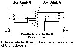
Connector Specifications (Adapter-female side)
| Adapter Pin No. | Signal |
|---|---|
| 1 | +5Vdc out |
| 2 (SW A-port) | Button 4 in |
| 3 (X A-port) | Position 0 in |
| 4 | Ground |
| 5 | Ground |
| 6 (Y A-port) | Position 1 in |
| 7 | Button 5 in |
| 8 | +5Vdc out |
| 9 | +5Vdc out |
| 10 (SW B-port) | Button 6 in |
| 11 (X B-port) | Position 2 in |
| 12 | Ground |
| 13 (Y B-port) | Position 3 in |
| 14 | Button 7 in |
| 15 | +5Vdc out |
Please see the LEGAL - Trademark notice.
Feel free - send a  for any BUG on this page found - Thank you.