 |

 IBM-AUSTRIA - PC-HW-Support 30 Aug 1999
 |
Preparing the Rack (Netfinity 7000 - 8651)
Preparing the Rack

 Four people are required to move or lift the server.
In this section, you will use the following parts:
- IBM Installation Template
- Two slide-bracket nut bar assemblies
- One cable-management arm
- Eight M4x8 pan head screws
- Eight M6x16 screws
- One cable management arm
- One arm to shuttle (CEC) bracket with cap fastener
- Two M6x16 hex flange screws
- Two M6 hex flange nuts
- Two 10-32 x 0.5-Inch screws
- One nut bar
- Two M6x16 hex flange screws
- Four M6x16 screws
- Six nut clips
 To ensure rack stability, plan the installation of servers
in the rack starting from the bottom.
To ensure rack stability, plan the installation of servers
in the rack starting from the bottom.
To attach the mounting hardware to the rack:
- Remove the rack front door. Refer to the rack
documentation for instructions.
- Mark the positions of the slide-bracket assemblies,
bezel brackets, and the cable-management arm on
the rack:
- Position the installation template on the front
mounting rails on the rack, aligning the holes.
- Mark the holes for the slide-bracket assemblies
and bezel brackets.
- Install two cage nuts to each of the two front
mounting brackets for the bezel brackets.
- Attach the template to the rear mounting rails.
Mark the locations for the slide-bracket
assemblies and cable-management arm.
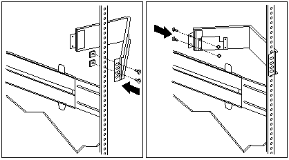
- Attach a slide-bracket assembly to the front of the rack:
NOTE:
- Get another person to help you attach the slide-bracket assemblies to the rack.
- The slide-bracket assemblies can be installed on either the left or right side of the rack.
- Refer to the illustrations for examples of the proper alignment of the slide-bracket assemblies.
- Position the slide-bracket assembly behind the
mounting rail so that the slides will extend out
from the front of the rack.
- If necessary, loosen the screws at the rear of the
slide bracket assembly and adjust the length of
the slide-bracket to fit the mounting rail. Tighten the screws.
- Position a nut bar behind the slide-bracket assembly.
- Insert screws (16M by 16 mm) through the
mounting rail, slide-bracket assembly, and nut
bar. Do not tighten the screws.
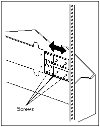
- Attach the slide bracket assembly to the rear of the rack:
- Position the slide-bracket assembly inside the mounting rail.
- Position a nut bar behind the slide-bracket assembly.
- Insert screws through the mounting rail, slide-bracket assembly, and nut bar.
Do not tighten the screws.
- Attach the other slide-bracket assembly to the front
and rear of the rack.
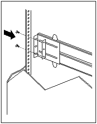
- Push the slide-bracket assemblies to the outermost
positions on the rack.
- Tighten all screws to secure both slide-bracket
assemblies.
If you are using a torque screwdriver,
use the following torque setting: 8-11 Nm (70.8-97.0 in/lbs).
- Attach the cable-management arm to the rear of the rack:
- Position the cable-management arm bracket on the outside of the mounting rail.
- Insert screws (M6 by 16 mm) through the cable-management arm bracket, mounting rail,
and cage nuts. Tighten the screws.
- Position the server bracket on the cable-management arm.
- Insert screws through the cable-management arm and the server bracket. Tighten the screws.
Back to 
More INFORMATION / HELP is available at the IBM-HelpCenter
Please see the LEGAL - Trademark notice.
Feel free - send a  for any BUG on this page found - Thank you.