| System Board |
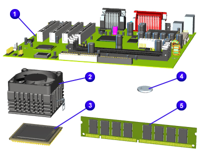
| System Board |
| JUMPER & SWITCH INFORMATION Jumper Settings |
| Jumper 3 | |
| CMOS Normal | CMOS Clear |
| pins 1-2 | pins 2-3 |
| Jumpers 4-6 | |||
| JP4 | JP5 | JP6 | CPU/Host Ratio |
| ON | ON | OFF | 2.5 |
| OFF | ON | OFF | 3.0 |
| ON | OFF | OFF | 2.0 |
| OFF | OFF | OFF | 1.5/3.5 |
| ON | ON | ON | 4.5 |
| OFF | ON | ON | 5.0 |
| ON | OFF | ON | 4.0 |
| OFF | OFF | ON | 5.5 |
| Jumpers 12-15 | CPU BUS SPEED | |||
| ON | OFF | OFF | OFF | 66.6mhz |
| OFF | ON | ON | OFF | 95mhz |
| OFF | OFF | ON | OFF | 97mhz |
| ON | ON | ON | OFF | 100mhz |
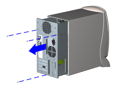
REMOVAL & REPLACEMENT PROCEDURES - BEFORE YOU BEGIN
To prepare the computer for removal and replacement procedures, complete the following steps:
| 1 | Remove any diskette, compact disc, or tape from the computer. |
| 2 | Turn off the computer and any peripheral devices that are connected to the computer. |
| CAUTION: The computer power switch should be turned off before you disconnect any cables. |
| 3 | Disconnect the power cord from the electrical outlet, and then from the computer. |
| 4 | Disconnect all peripheral device cables from the computer. |
IMPORTANT: During disassembly, label each cable as you remove it. Be sure to note its position and routing.
 |
| ||||||||||||||
 |
| ||||||||||||
 |
| ||||||||||
 |
| ||||||||||||
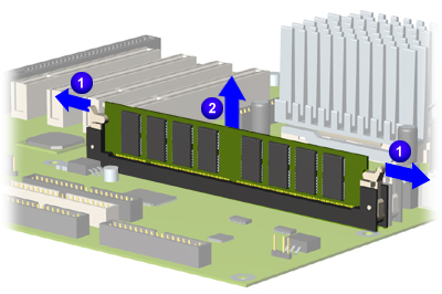 |
Replacement To replace the DIMM, reverse this procedure | ||||||
 |
|
|||||||||||||