| JUMPERS
Presario 5800 Models with Celeron
System Board
This board has no jumper settings except for
clearing CMOS.
Jumper location
JP1 |
CMOS
Jumper Settings |
| CMOS Normal |
CMOS Clear |
| Pins 1-2 |
Pins 2-3 |
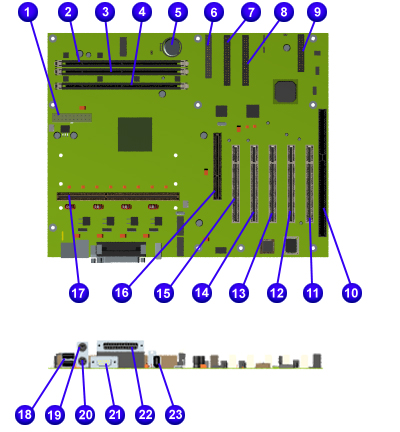
Presario 5800 Models
with Athlon System Board
Compaq Presario 5800
Series System Board: External Connectors |
|
Function |
Description |
Designator |
|
Serial |
DSUB 9-Pin |
J25 |
|
Parallel |
DSUB 25-Pin |
J25 |
|
USB Port |
Dual USB Connector |
J23 |
|
Keyboard |
Miniature 6-Pin |
1/2 J24 |
|
Mouse |
Miniature 6-Pin |
1/2 J24 |
|
CMOS Clear |
3-Pin Header |
J3 |
|
DIMM Sockets |
168-Pin DIMM |
S1,S2,S3 |
|
Button/Light Board |
7-Pin Header |
J1 |
|
Power Supply |
20-Pin ATX Power
Header |
J8 |
|
Replacement Battery |
Battery Holder
(CR2032 - battery type) |
B1 |
|
Primary IDE Drive
(Hard Drive) |
40-Pin Header, Key 20 |
J6 |
|
Secondary IDE Drive
(CD Drive) |
40-Pin Header, Key 20 |
J7 |
|
Diskette Drive |
34-Pin Header |
J5 |
|
PCI Slots |
PCI Slot 1-5 |
J16,
J17, J18,J19, J20 |
| |
CPU Fan |
Header |
J9 |
| |
System Fan |
Header |
J11 |
| |
1394 Connector |
Connector |
J22 |
| |
AGP Slot |
AGP Slot |
J12 |
| |
Processor |
Processor Slot |
J10 |
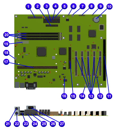
Presario 5800 Models with Pentium III
System Board
5800 Models with Pentium III System
Board: Connectors and Jumpers |
|
Function |
Description |
Designator |
| 1 |
Front I/O Connector |
|
J11 |
| 2 |
Parallel Port
Connector |
|
J8 |
| 3 |
Primary IDE Drive |
|
J12 |
| 4 |
Secondary IDE Drive |
|
J13 |
| 5 |
Diskette Drive |
|
J14 |
| 6 |
Fan Connector |
4-Pin |
J16 |
| 7 |
Fan Connector |
3-Pin |
J20 |
| 8 |
Button Board |
|
J10 |
| 9 |
CMOS Jumper |
|
JP1 |
| 10 |
RTC Battery |
Battery holder |
BT1 |
| 11 |
ISA Slot |
ISA Connector |
ISA1 |
| 12 |
On-board Audio Disable |
|
JP6 |
| 13 |
PCI Slots |
PCI Connector |
PCI 1 to 5 |
| 14 |
CD Audio |
|
J17 |
| 15 |
AGP Slot |
|
AGP1 |
| 16 |
Frequency Multiple Jumpers |
|
JP2 |
| 17 |
Slot 1 |
|
J18 |
| 18 |
Heatsink Fan Connector |
|
J15 |
| 19 |
ATX Power Supply Connector |
|
J9 |
| 20 |
DIMM |
168-pin DIMM |
DIMM
1 to 3 |
| 21 |
Mouse |
Mini 6-pin |
J1 (Upper) |
| 22 |
Keyboard |
Mini 6-pin |
J1 (Lower) |
| 23 |
USB (2) |
|
J2 |
| 24 |
MIC Connector |
Mini stereo |
J3A |
| 25 |
Line in |
Mini stereo |
J3B |
| 26 |
Audio Connector (line out) |
Mini stereo |
J3C |
| 27 |
Serial Port |
|
J4 |
| 28 |
1394 Connector |
6-pin 1394 connector |
J7 |
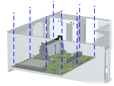
REMOVAL/REPLACEMENT
PROCEDURES
System board may vary from the one shown.
|
Removing the System Board
|
| 1. |
Complete the preparation for
disassembly procedures. |
| 2. |
Remove the Chassis. |
| 3. |
Disconnect Baffle from fan by
sliding tabs out of the slots on both sides of baffle, then lift baffle up. |
| 4. |
Remove the Graphics Board (on
selected models only). |
| 5. |
Remove the Fax/Modem. |
| 6. |
Remove Networking Interface Card
(on select models only). |
| 7. |
Remove
the Audio Card (on select models only). |
| 8. |
Remove the Memory. |
| 9. |
Remove the Processor. |
| 10. |
Remove the Processor Retention
Clips. |
| 11. |
Disconnect the System Board
Cables. |
| NOTE: |
Be sure to remove components
such as DIMMs, processor, and
video memory before replacing
the system board. |
| 12. |
Remove nine screws from the
System Board. |
| 13. |
Slide System Board toward drive
bay and lift from the computer. |
|
| Replacement |
|
To replace the system board,
reverse the removal procedure. |
|
|