100MHz
System Bus
Technology Description:
Compaq Presario products (desktop and
towers with 350MHz and above processor speed) will contain the latest 100MHz System Bus.
The new bus offers higher performance by breaking the old 66MHz barrier.
This new bus design connects the power of
faster processors with the super fast 100MHz SyncDRAM for an unprecedented level of PC
performance. The 100MHz System Bus speed is 50% faster than the 66MHz System Bus. The
result of this seamless integration of two outstanding technologies is the delivery of new
levels of performance for advanced media and communications software, including powerful,
realistic graphics, imaging capabilities and video conferencing. Traditional applications
like word-processing and spreadsheet run faster as well because of these new design
improvements.
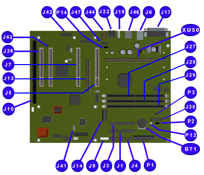
Presario 5600 Series
System Board with Homenet TUT Daughter Board and P3 Jumpers
Compaq Presario 5600 Series System
Board: External Connectors |
| Function |
Description |
Designator |
| Replacement Battery |
4-Pin Header, Key 2 |
BT1 |
| Primary IDE Drive
(Hard Drive) |
40-Pin Header, Key 20 |
J1 |
| Secondary IDE Drive
(CD Drive) |
40-Pin Header, Key 20 |
J3 |
| Diskette Drive |
34-Pin Header |
J4 |
| PCI Slot |
PCI Slot |
J5 |
| Keyboard |
Miniature 6-Pin |
1/2J6 |
| Mouse |
Miniature 6-Pin |
1/2J6 |
| PCI Slot |
26-Pin Header, Key 7 |
J7 |
| Button Board Header |
20-Pin Header |
J9 |
| Combo ISA Slot |
ISA Slot |
J10, J36 |
| Video Memory
Expansion |
30-Pin Small Header |
J13 |
| internal Line In (CD Drive) 3.3 V Connector |
4-Pin Header, Key 2 |
J14 |
| Parallel IO Connector |
DSUB 25-Pin |
J17 |
| USB Port |
USB Connector |
J19 |
| DIMM Socket |
168-Pin DIMM |
J27, J28, J29 |
| ITP Test Header |
4-Pin, Key 2 |
J30 |
| Ethernet IO connection |
RJ45 |
J32 |
| Walk-up USB & 1394 |
|
J41 |
| Homenet TUT Daughter Board (Add in board) |
30-Pin Header |
J42 |
| PCI Slot |
34-Pin Edge |
J43 |
| RJ11 Telephone IO Connector |
RJ11 |
J44 |
| Serial IO Connector |
9-Pin Header |
J45 |
| Power Supply |
12-Pin ATPWR Header |
P1,
P2 |
| External Battery |
4-Pin Header, Key 2 |
P2 |
| CPU Clock Multiplier |
6-Pin Header |
P3 |
| CMOS Jumper |
3-Pin Header |
P12 |
| Fan Connector |
4-Pin Header, Key 2 |
P14 |
P3 Settings for Processor Frequency Selection
(at 66MHz Bus Speed) |
| Frequency (MHz) |
200 |
233 |
266 |
300 |
333 |
| Jumpers A1-B1 |
On |
Off |
On |
Off |
On |
| Jumpers A2-B2 |
Off |
Off |
On |
On |
Off |
| Jumpers A3-B3 |
On |
On |
Off |
Off |
Off |
| |
P3 Settings for Processor Frequency Selection
(at 100MHz Bus Speed) |
| Frequency (MHz) |
300 |
350 |
400 |
450 |
500 |
| Jumpers A1-B1 |
On |
Off |
On |
Off |
On |
| Jumpers A2-B2 |
Off |
Off |
On |
On |
Off |
| Jumpers A3-B3 |
On |
On |
Off |
Off |
Off |
Removal
Replacement Procedures
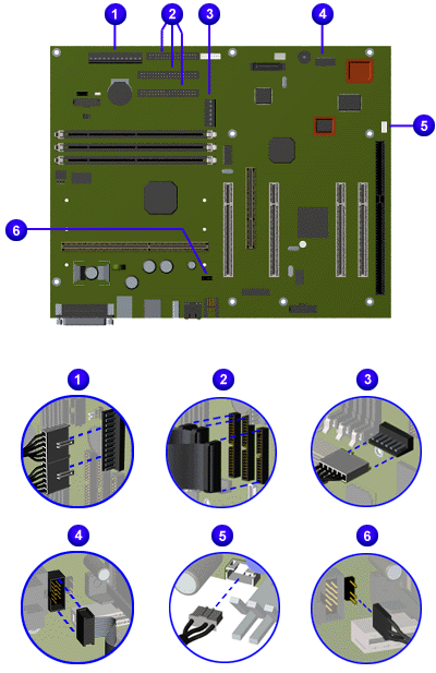
|
| Removal |
| 1. |
Power Cables, P1 system
board connector. |
| 2. |
Data Cables, J1, J3, J4
system board connectors. |
| 3. |
Power
Cable, J14 system board connector. |
| 4. |
Serial Port Cable, J8
system board connector. |
| 5. |
Audio Cable, P4 system
board connector. |
| 6. |
Fan Cable, P14 system
board connector. |
|
|
| Replacement |
| 1. |
To replace the system board
cables, reverse the removal procedure. |
|
|
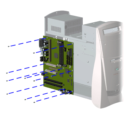
| Removal |
| 1. |
Perform the preparation
for disassembly procedures. |
| 2. |
Remove the hood. |
| 3. |
Remove the fan. |
| 4. |
Remove the video board. |
| 5. |
Remove the serial port. |
| 6. |
Remove the processor. |
| 7. |
Remove the processor goal
posts. |
| 8. |
Disconnect the system
board cables. |
| 9. |
Remove nine screws from
the system board. |
| 10. |
Slide system board forward
and lift from the computer. |
|
| Replacement |
|
To replace the system
board, reverse the removal procedure. |
| NOTE: |
Be sure to remove
components such as DIMMs, processor, and video memory before replacing the System Board. |
|
|