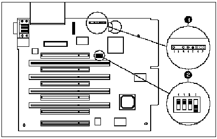
Configuring the System Board
 |
|
#
|
Item
|
Function
|
| 1 |
JP1 |
Used for installing an external battery to replace the real-time clock
battery. |
| 2 |
SW1 |
Used for enabling or disabling:
-
Hot spare boot
-
Power-On Password
|
|
Jumper (JP1)
JP1 pins: J1-J7; provide the pin settings required for installing an
external battery. The factory (default) settings are indicated as marked
|
Jumper Settings (JP1) External Battery
|
|
Pins
|
Function
|
Description
|
|
1-4
|
Battery
|
External battery connection |
|
5-6
|
Battery
|
External battery jumper |
|
6-7
|
Battery
|
Internal battery jumper (Default) |
Switch Module (SW1)
SW1 contains four switches: S1-S4. The table illustrates the switch
settings for S1 (hot spare boot) and S2 (Power-On Password). S3 and S4
are reserved and must be OFF. The factory (default) settings are indicated
as marked
|
SW1 Settings
|
|
Feature
|
Description
|
S1
|
S2
|
S3
|
S4
|
| Hot Spare Boot |
Disabled |
OFF |
- |
OFF |
OFF |
| |
Enabled (Default) |
ON |
- |
OFF |
OFF |
| Power-On Password |
Disabled |
- |
ON |
OFF |
OFF |
| |
Enabled1 (Default) |
- |
OFF |
OFF |
OFF |
| Note1: Enabled - allows a password
to be set. |

