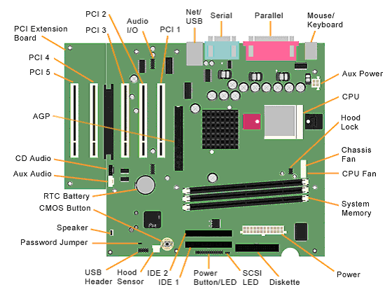

| BAT1 | External battery | J26 | Power-On switch and LED connector |
| DIMM 1-2 | Memory slots | J28 | Primary IDE connector |
| J9 | Aux audio in connector | J30 | Chassis intrusion connector |
| J10 | CD audio in connector | J31 | Secondary IDE connector |
| J11 | Modem in (audio) connector | J32 | Diskette drive connector |
| J16 | AGP card socket | J33 | Chassis fan |
| J17 | Processor | J34 | System fan (power supply) |
| J18 | Wake on Ring | JP4 | ROM BIOS lock |
| J19 | Processor (CPU) fan | JP5 | Safe mode |
| J20 | Wake on LAN connector | JP6 | Clear CMOS jumper |
| J25 | Main power connector | PCI 1-3 | PCI card sockets |

To clear and reset the configuration, perform the following procedure:
|
|
|
| CAUTION:
The power cord must be disconnected from the power
source before pushing the Clear CMOS
Button (NOTE: All LEDs on the board should be OFF). Failure to do so may damage the system board |
|
|
|
|