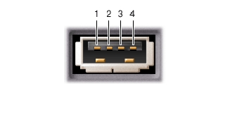
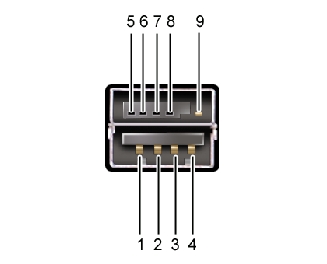
 USB Connector
Dell™ Latitude™ D800 Service Manual
|
Pin |
Signal |
|---|---|
1 |
|
2 |
|
3 |
|
4 |
|
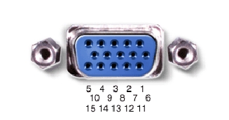
Pin |
Signal |
Pin |
Signal |
|---|---|---|---|
1 |
9 |
||
2 |
10 |
||
3 |
11 |
||
4 |
12 |
||
5 |
13 |
||
6 |
14 |
||
7 |
15 |
||
8 |
|
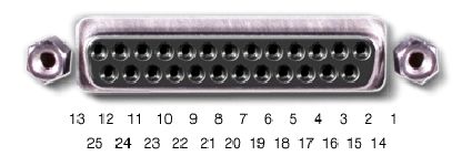
Pin |
Signal |
Pin |
Signal |
|---|---|---|---|
1 |
10 |
||
2 |
11 |
||
3 |
12 |
||
4 |
13 |
||
5 |
14 |
||
6 |
15 |
||
7 |
16 |
||
8 |
17 |
||
9 |
18-25 |
|
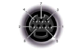
S-Video | |
|---|---|
|
Pin |
Signal |
1 |
|
2 |
|
3 |
|
4 |
|
|
Composite Video | |
|---|---|
|
Pin |
Signal |
5 |
|
6 |
|
7 |
|
|
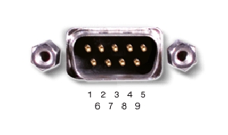
Pin |
Signal |
Pin |
Signal |
|---|---|---|---|
1 |
6 |
||
2 |
7 |
||
3 |
8 |
||
4 |
9 |
||
5 |
|
|
Pin |
Signal |
Pin |
Signal |
|---|---|---|---|
1 |
8 |
||
2 |
9 |
||
3 |
10 |
||
4 |
11 |
||
5 |
12 |
||
6 |
13 |
||
7 |
14 |