 Preparing to Work Inside the
Computer
Preparing to Work Inside the
Computer
Dell™ Latitude™ C810 Service Manual
Preparing to Work Inside the
Computer
 |
NOTICE: Only a certified service technician should perform repairs on your computer. Damage due to servicing that is not authorized by Dell is not covered by your warranty. |
|
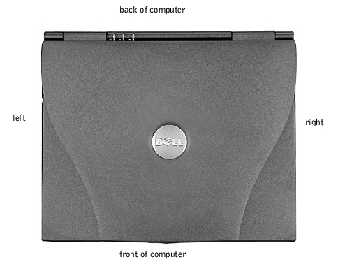
NOTICE: To avoid damaging the computer, perform the following steps before you begin working inside the computer. |
 |
NOTE: Before turning off the computer, make sure the computer is not in a power-management mode. |
|
NOTICE: To avoid component damage, always remove any installed batteries before you service the computer. |
The procedures in this manual require the following tools:
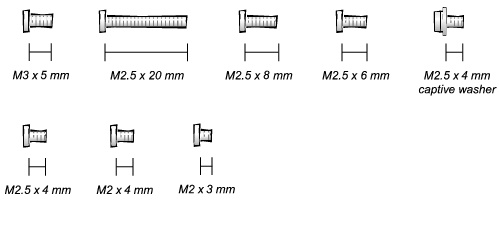
When you are removing and replacing components, photocopy the placemat as a tool to lay out and keep track of the component screws.The placemat provides the number of screws and the sizes.
|
NOTICE: When reinstalling a screw, you must use a screw of the correct diameter and length. Make sure that the screw is properly aligned with its corresponding hole, and avoid overtightening. |
Hard Drive Door Security: M3.0 x 5 mm (1 each)
| Keyboard to Bottom Case Assembly: M2.5 x 20 mm (4 each; one in memory door and one in mini-PCI door)
| Display to Base: M2.5 x 6 mm (3 each; 2 at back of system; 1 at flex cable strain relief)
|
Display Bezel: Rubber screw covers (4 each) Plastic screw covers (2 each) M2.5 x 4 mm (6 each)
| Display Panel to Display Mounting Bracket: M2.0 x 3 mm(6 each)
Flex Cable Mounting Bracket to Top Cover: M2.5 x 4 mm (1 each)
| Video Graphics Board: M2.5 x 8 (3 each)
|
Palmrest to M2.5 x 20 mm (9 each)
Palmrest Bracket:
| System Board: M2.5 x 4 mm captive washer
M2.5 x 20 mm (1 each)
| LED Board: M2.0 x 4 mm (2 each)
|
Fan Assembly: M2.0 x 4 mm (3 each)
| RJ-11/RJ-45 Board Assembly: M2.5 x 4 mm (1 each)
|