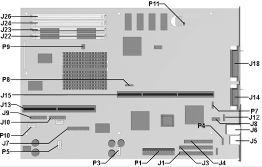
9000 System Board
Internal Connectors I External Connectors I Jumpers
| Function | Description | Designator |
| Audio In Connector | 4-Pin Header | P3 |
| Audio Out/Power Up Reset | 14-Pin Header Key 6 | J10 |
| Button Board | 20-Pin Header | J9 |
| Cache Socket | 160-Pin DIMM | J13 |
| CD Audio IN | 4-Pin Header, Key 2 | P5 |
| Clock Multiplier | 6-Pin Header | P9 |
| Clock Speed | 5-Pin Header | P8 |
| CMOS | 2-Pin Header | P11 |
| Diskette Drive | 34-Pin Header | J4 |
| Fan | 4-Pin Header, Key 2 | P10 |
| IDE Drive (Primary/Secondary) | 40-Pin Header, Key 20 | J1, J3 |
| Microphone (Front panel) | 4-Pin Header | P4 |
| Power Supply | 12-Pin ATPWR Header | P1 |
| Replacement Battery | 4-Pin Header, Key 2 | P7 |
| Riser Board | 212 Pin Connector | J15 |
| Serial | 10-Pin Header, Key 10 | J8 |
| SIMM Sockets | 72-Pin SIMM | J26, J24, J23, J22 |
| USB Port | Dual USB | J12 |
| Wavetable Connector | 26-Pin Header, Key 7 | J7 |
| Function | Description | Designator |
| Joystick/MIDI | DSUB 15-Pin 2 Row | J14 |
| Keyboard | Miniature 6-Pin | 1/2 J6 |
| Mouse | Miniature 6-Pin | 1/2 J6 |
| Parallel | DSUB 25-Pin | J18 |
| Jumper | Pins |
Function |
| P7 |
|
Replacement Battery Connector |
| P8 Bus Speed Select |
1-2 |
50 MHz CPU External Bus Frequency (PCI 25 MHz) |
2-3 |
60 MHz CPU External Bus Frequency (PCI 30 MHz) | |
3-4* |
66 MHz CPU External Bus Frequency (PCI 33 MHz) | |
4-5 |
55 MHz CPU External Bus Frequency (PCI 27.6 MHz) | |
| P9 CPU Clock | A1-A2 |
2/3 x |
A2-A3 |
1/2 x | |
A2-A3 |
2/5 x | |
A1-A2* |
1/3 x | |
| P11 CMOS Clear |
1-2* |
Secure CMOS Power Remove jumper for 10 seconds and reinstall to clear CMOS |
| *Default | ||