
|
|
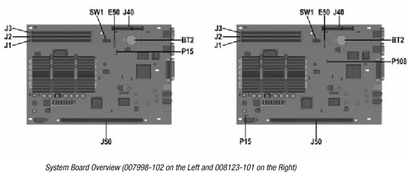
| Note: *Board 007998-102 has the P15 connector located near the battery. Board 008123-101 has the P15 connector located near the riser board connector. |
 |
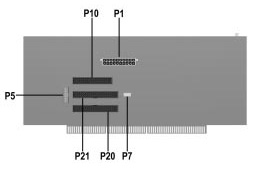 |
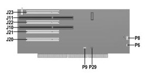
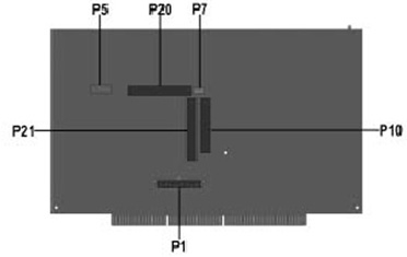
| Connectors, Jumpers, and Switches | |||
| Item | Description | Item | Description |
| BT2 | External battery | J21 | PCI connector slot |
| E50 | CMOS | J22 | PCI combination slot |
| J1 | DIMM 1 | J23 | PCI combination slot |
| J2 | DIMM2 | P8 | Fan |
| J3 | DIMM3 | P6 | Speaker |
| J40 | AGP connector | P29 | SCSI LED header |
| J50 | Riser board socket | P9 | NIC Remote Wakeup |
| P15 | Fan (thermal cable) | P10 | Diskette drive connector |
| SW1 | Switch 1, S1 through 6 | P1 | Power supply connector |
| J10 | ISA combination slot | P7 | CD audio connector |
| J11 | ISA combination slot | P20 | Primary IDE connector |
| J20 | PCI connector slot | P21 | Secondary IDE connector |
| P5 | Hood control, power switch, LEDs | ||
 |
|
|||||||||||||||||||||||||||||||||||||||||||||||||||||||||||||||||||||||||||||||||||||||||||||||||||||||||||||||||||||||
|
||||||||||||||||||||||||||||||||||||||||||||||||||||||||||||||||||||||||||||||||||||||||||||||||||||||||||||||||||||||||
|
||||||||||||||||||||||||||||||||||||||||||||||||||||||||||||||||||||||||||||||||||||||||||||||||||||||||||||||||||||||||
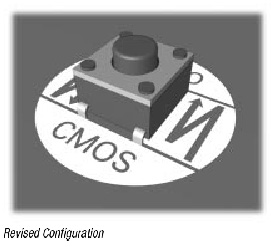
| (Revised Configuration - Revised Configuration refers to all models produced after June 23, 1999.) | |||
 |
|||
|
|
|||
|
|
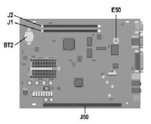
|||
| BT2 | External battery | J2 | DIMM2 |
| E50 | CMOS | J50 | Riser board socket |
| J1 | DIMM 1 | ||
| (Revised Configuration - Revised Configuration refers to all models produced after June 23, 1999.) | |||
 |
|
||
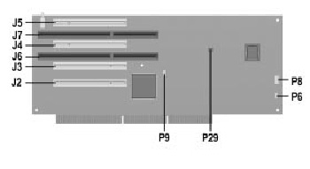
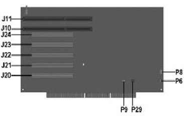
| Front Side of Desktop Riser Board (Revised Configuration) | Rear Side of Desktop Riser Board (Revised Configuration) | ||
| Connectors, Jumpers, and Switches | |||
| Item | Description | Item | Description |
| J2 | PCI connector slot | J7 | ISA combination slot |
| J3 | PCI connector slot | P6 | Speaker |
| J4 | PCI connector slot | P8 | Fan |
| J5 | PCI connector slot | P9 | NIC Remote Wakeup |
| J6 | ISA combination slot | P29 | SCSI LED header |
| (Revised Configuration - Revised Configuration refers to all models produced after June 23, 1999.) |
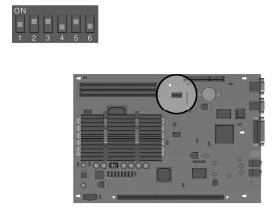
| As of 1/1/99 all Celeron, Pentium II, and Pentium III units >300 MHz ship with the processor speeds preset. These preset speeds will override any changes to switch settings on the system board. |
| (Revised Configuration - Revised Configuration refers to all models produced after June 23, 1999.) |
| The computer's configuration (CMOS) may occasionally be corrupted. If it does, it is necessary to clear the CMOS memory using switch SW50. To clear and reset the configuration, perform the following procedure: |
|
 |
 |
| Note: *Board 007998-102 has the P15 connector located near the battery. Board 008123-101 has the P15 connector located near the riser board connector. |
 |
 |
| Connectors, Jumpers, and Switches | |||
| Item | Description | Item | Description |
| BT2 | External battery | J21 | PCI connector slot |
| E50 | CMOS | J22 | PCI combination slot |
| J1 | DIMM 1 | J23 | PCI combination slot |
| J2 | DIMM2 | P8 | Fan |
| J3 | DIMM3 | P6 | Speaker |
| J40 | AGP connector | P29 | SCSI LED header |
| J50 | Riser board socket | P9 | NIC Remote Wakeup |
| P15 | Fan (thermal cable) | P10 | Diskette drive connector |
| SW1 | Switch 1, S1 through 6 | P1 | Power supply connector |
| J10 | ISA combination slot | P7 | CD audio connector |
| J11 | ISA combination slot | P20 | Primary IDE connector |
| J20 | PCI connector slot | P21 | Secondary IDE connector |
| P5 | Hood control, power switch, LEDs | ||