 |
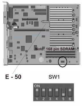
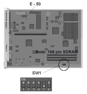
| E - 50 |
| Pins |
Function |
Description |
| 1 - 2 |
Battery |
Internal Battery Jumper |
| 2 - 3 |
Battery |
External Battery |
| 5 - 6 |
Clear CMOS* |
Relocate Battery Jumper and Return |
| 9 - 12 |
Battery |
External Battery Connection |
| * Must also remove the AC power cord |
|
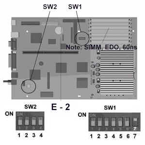
| Switch
Block SW1 |
| Processor |
S1 |
S2 |
S3 |
S4 |
S5 |
S6 |
| 166 |
* |
ON |
ON |
X |
ON |
** |
| 200 |
* |
OFF |
ON |
X |
ON |
** |
| 233 |
* |
OFF |
OFF |
X |
ON |
** |
*Power-On Password, ON = Disabled; OFF = Enabled
Default = OFF |
**AC Cord Connection
OFF = Main P/S is OFF, Aux P/S is ON
ON = Main P/S is ON, Aux P/S is ON |
|
Disabling Power-On Password
The Power-On Password feature
is enabled or disabled by moving the SW1 position on located on the system
board.
Clearing Configuration and Password
The computer's configuration
(CMOS) may occasionally be corrupted. When it does, it is necessary to
clear the CMOS memory.
To clear and reset the configuration
perform the following procedure:
-
Unplug the power cord from the unit and
remove the cover.
-
Remove the E50 jumper from pins 1 and
2 and place on pins 5 and 6.
-
Replace the E50 jumper on pins 1 and 2.
When jumper E50 is removed, the password
becomes invalid because the password is stored in the configuration memory.
You will need to reset the password.
Changing the Real-Time Clock (RTC) Battery
When installing the replacement
RTC Battery, the battery connector is keyed and should be connected to
the pins on the E9 battery header connector.
|