5900z System Board

JUMPERS | REMOVAL/REPLACEMENT PROCEDURES

* Presario 
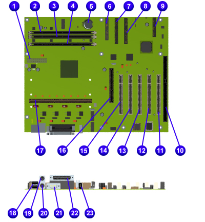
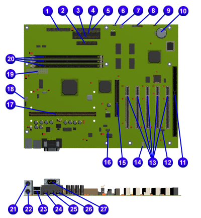
5900Z systems manufactured after January 31, 2000 will ship with a new system board. The board will have two Memory DIMM sockets, 
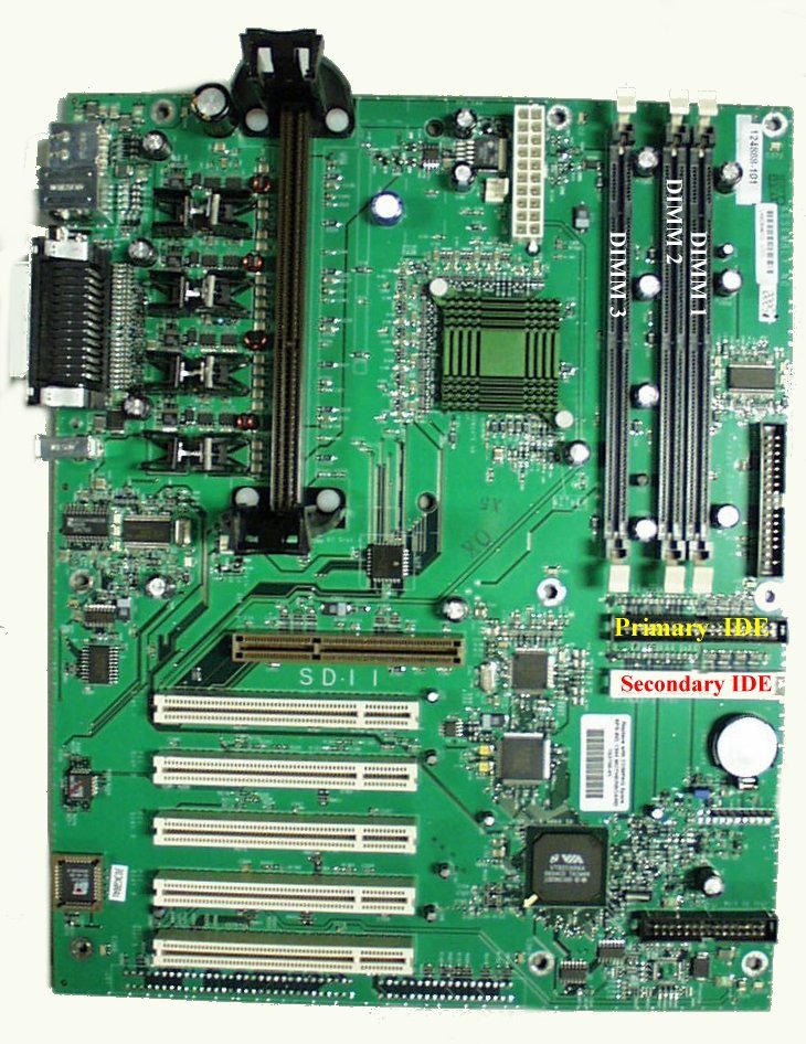
unlike the original board which has three.

Supported memory upgrade on the new board will be up to 512MB by using two 256MB DIMMS, although Compaq will only offer a maximum of 384MB, using one 256MB and one 128MB DIMMS.

If it is determined that a customer needs a system board replacement, and their serial number shows the system was built after the 4th week of January, replace the board with spare part number 166049-101.
To determine if the unit was built after the 4th week of January, look at the second, third and fourth digits of the serial number. The second digit determines the year the unit was built. The third and fourth digit determines the week.

X004CMPZXXXX

The second digit (0) determines the year the unit was built - 2000; and the third and fourth digits (04) determines the week the unit was built (week 4).
If the serial number shows the unit was built before week 4 of January, replace the system board with spare part number 153756-101.

JUMPERS

Presario 5900 Models with Celeron System Board

This board has no jumper settings except for clearing CMOS.  

Jumper location JP1

CMOS Jumper Settings

CMOS Normal CMOS Clear
Pins 1-2 Pins 2-3

Presario 5900 Models with Athlon System Board

sysbrdamd.jpg


        (132289 bytes)

Compaq Presario 5900 Series System Board: External Connectors

Function Description Designator
Serial DSUB 9-Pin J25
Parallel DSUB 25-Pin J25
USB Port Dual USB Connector J23
Keyboard Miniature 6-Pin 1/2 J24
Mouse Miniature 6-Pin 1/2 J24
CMOS Clear 3-Pin Header J3
DIMM Sockets 168-Pin DIMM S1,S2,S3
Button/Light Board 7-Pin Header J1
Power Supply 20-Pin ATX Power Header J8
Replacement Battery Battery Holder (CR2032 - battery type) B1
Primary IDE Drive (Hard Drive) 40-Pin Header, Key 20 J6
Secondary IDE Drive (CD Drive) 40-Pin Header, Key 20 J7
Diskette Drive 34-Pin Header J5
PCI Slots PCI Slot 1-5 J16, J17, J18,J19, J20
  CPU Fan Header J9
  System Fan Header J11
  1394 Connector Connector J22
  AGP Slot AGP Slot J12
  Processor Processor Slot J10

Presario 5900 Models with Pentium III System Board

sysbrdp3.jpg


        (146526 bytes)

5900 Models with Pentium III System Board: Connectors and Jumpers

Function Description Designator
1 Front I/O Connector J11
2 Parallel Port Connector J8
3 Primary IDE Drive J12
4 Secondary IDE Drive J13
5 Diskette Drive J14
6 Fan Connector 4-Pin J16
7 Fan Connector 3-Pin J20
8 Button Board   J10
9 CMOS Jumper JP1
10 RTC Battery Battery holder BT1
11 ISA Slot ISA Connector ISA1
12 On-board Audio Disable   JP6
13 PCI Slots PCI Connector PCI 1 to 5
14 CD Audio J17
15 AGP Slot AGP1
16 Frequency Multiple Jumpers   JP2
17 Slot 1   J18
18 Heatsink Fan Connector   J15
19 ATX Power Supply Connector   J9
20 DIMM 168-pin DIMM DIMM
1 to 3
21 Mouse Mini 6-pin J1 (Upper)
22 Keyboard Mini 6-pin J1 (Lower)
23 USB (2) J2
24 MIC Connector Mini stereo J3A
25 Line in Mini stereo J3B
26 Audio Connector (line out) Mini stereo J3C
27 Serial Port   J4
28 1394 Connector 6-pin 1394 connector J7

REMOVAL/REPLACEMENT PROCEDURES

System board may vary from the one shown.

systemboard.jpg (76147 bytes)

Removing the System Board

1. Complete the preparation for
disassembly procedures.
2. Remove the Chassis.
3. Disconnect Baffle from fan by sliding tabs out of the slots on both sides of baffle, then lift baffle up.
4. Remove the Graphics Board (on selected models only).
5. Remove the Fax/Modem.
6. Remove Networking Interface Card (on select models only).
7. Remove the Audio Card (on select models only).
8. Remove the Memory.
9. Remove the Processor.
10. Remove the Processor Retention Clips.
11. Disconnect the System Board Cables.
NOTE: Be sure to remove components
such as DIMMs, processor, and
video memory before replacing
the system board.
12. Remove nine screws from the System Board.
13. Slide System Board toward drive bay and lift from the computer. 

Replacement
To replace the system board,
reverse the removal procedure.