Quick Installation Chart
For your convenience, this chart lists all the CPUs supported by P2LXB and their corresponding jumper setting.
| CPU Model | Ratio | JF0 | JF1 | JF2 |
| 233/66 | 3.5x | 1-2 | 2-3 | 2-3 |
| 266/66 | 4.0x | 2-3 | 1-2 | 1-2 |
| 300/66 | 4.5x | 2-3 | 1-2 | 2-3 |
| 333/66 | 5.0x | 2-3 | 2-3 | 1-2 |
***We support the over specification operation, please see session 3.4.16 for more information.
Panel Connectors
| JFRNT1 Connector | Function |
| GREEN LED | Suspend Mode LED |
| PWR LED | Power LED |
| KEYLOCK | Keylock Switch |
| SPKR | Speaker |
| RESET | Reset Switch |
| IDE LED | HDD LED |
| PWR BTN | ATX Power Button Connector |
| SMI S/W | Sleep Switch |
P2LXBMotherboard User's ManualProduct Name: P2LXBManual Revision: English, 1.01Trademarks
Intel and Pentium II are trademarks of Intel Corporation
Award is a trademark of Award Software International Inc.
MS-DOS, Windows 95, Windows 98 and Windows NT are registered trademarks of Microsoft Corporation
Novell is a trademark of Novell Corporation
All other brand and product names are trademarks or registered trademarks of their respective companies.
Table of Contents
Chapter 1. Introduction
1.1 Product Overview
1.2 Specifications
1.3 Content
1.4 System Board Layout
Chapter 2. Hardware Setup
2.1 Installation Procedure
2.1.1 Jumper Settings
2.1.2 Clearing the CMOS
2.1.3 CPU Voltage Setting
2.1.4 CPU Frequency Selection
2.2 Installation of CPU
2.3 Installation of Memory
2.3.1 Installation of 168-pin DIMM
2.3.2 Removal of 168-pin DIMM
2.3.3 Memory Configuration
2.4 I/O Connections/Panel Connections
2.4.1 ATX Power Connector,AT Power Connector
2.4.2 Chassis & CPU Fan Connectors
2.4.3 Infrared Connector
2.4.4 Wake-up on LAN Connector
2.4.5 Creative��s SB_LINK Sound Connector
2.4.6 Floppy Disk Drive Connector
2.4.7 Primary/Secondary IDE Connector
2.4.8 PS/2 Mouse Port
2.4.9 Serial Port
2.4.10 Printer Port
2.4.11 USB Connectors
2.4.12 Panel Connection
Chapter 3. BIOS Setup
3.1 CMOS Setup Utility
3.2 Standard CMOS Setup..
3.3 BIOS Features Setup
3.4 Chipset Features Setup
3.5 Power Management Setup
3.6 PNP/PCI Configuration Setup
3.7 Integrated Peripherals
3.8 Load BIOS Defaults
3.9 Load Setup Defaults
3.10 Supervisor/User Password
3.11 IDE HDD Auto Detection
3.12 Exit CMOS Setup Utility
Chapter 1. Introduction
1.1 Product Overview
Thank you for purchasing the P2LXB motherboard. This motherboard utilizes Intel's latest technology, namely 440LX AGPset chipset. We have conducted a motherboard compatibility test with a variety of hardware and software, such as CPUs, memory, display cards, CD ROMs, Novell, MS Office....etc and compliance with Year 2000.
We have set high standards on our quality control, with absolute confidence, we believe this product is the wisest choice.
This manual is composed of three sections. The first section is the introduction of this motherboard, and the second section explains the proper procedure to setup the motherboard, the third section provides information on how to setup the CMOS.
Features:
- Support Desktop Management Interface (DMI) through BIOS.
- Support Accelerated Graphics Port (AGP) cards for high performance.
- Modem Remote Ring On.
- Wake up on LAN.
- RTC Wake Up Alarm: Program the date/time to wake up your system.
- CPU Thermal Protection: Warning when the CPU temperature is too high (optional).
- CPU & System Voltage Monitoring (optional).
- CPU & Chassis fan speed monitoring (optional).
- Support Advanced Configuration Power Interface (ACPI).
- BIOS Green feature function, and Plug & Play Flash ROM.
1.2 Specifications
| CPU: | - | Supports Intel Pentium II Processors 233~333 MHz and Celeron Processors. |
| Chipset: | - | Intel 440LX AGPset chipset |
| DIMM: | - | Supports 3.3V EDO or SDRAM in 3 168-pin banks,each bank consists of 1x168-pin 64-bit DIMM socket, which can support memory sizes of 8/16/32/64/128 MB modules. |
| - | Supports up to a maximum of 384 MB with SDRAM & 768 MB with EDO system memory. |
| IDE: | - | Dual channel PIO and PCI Bus Master IDE ports support up to 4 EIDE devices for HDD or CD-ROM |
| - | Supports PIO Mode 4 with data transfer rate up to 14 MB/Sec |
| - | Supports Ultra DMA 33 (UDMA) with data transfer rate up to 33 MB/Sec |
| BIOS: | - | Award BIOS V4.51 with built-in Anti-Virus, DMI support, and green function (Plug-and-Play BIOS) |
| - | Supports CD-ROM, SCSI, and LS120/ZIP boot up |
| I/O Devices: | - | One FDD control port supports two of the 5.25" or 3.5" floppy drives up to 2.88 MB. |
| - | Two high-speed 16550 UART compatible serial ports |
| - | One parallel ports with ECP/ EPP compatibility. |
| - | One PS/2 mouse port |
| IR Port: | - | One IrDA/ASKIR compatible Infrared interface port. (Cable optional) |
| USB Ports: | - | Two Universal Serial Bus (USB) ports support up to 127 peripheral devices. |
| Power Connector: | - | Supports AT & ATX Power supply. |
| - | Supports Modem remote Ring-On function when using ATX power supply. |
| - | Supports software power off function |
| - | Supports RTC Wake-Up. |
| - | Supports Wake up on LAN. |
| Others: | - | Supports System Monitor function (optional) |
| - | Supports Creative��s Sound Blaster 16 compatibility for real-mode DOS games. |
| Expansion Slots: | - | Four 32-bit PCI expansion slots |
| - | Two 16-bit ISA expansion slots |
| - | One 32-bit AGP expansion slot |
| Operating System: | - | Supports Windows 95/98, Windows NT, MS-DOS V. 6.22, OS/2, Novell, Unix, SCO UNIX..... |
| Dimension: | - | 220 mm x 250 mm Baby AT Form factor |
1.3 Content
The P2LXB motherboard box contains the following items:
- One P2LXB Motherboard
- One IDE Ribbon Cable
- One Floppy Ribbon Cable
- A Set of Serial Ribbon Cable
- A Parallel Port and A PS/2 Mouse Port
- One Retention mechanism
- One Driver CD
- User's Manual & Quick Installation Chart
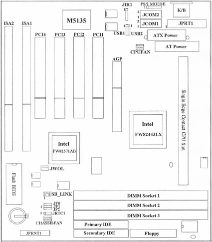
1.4 MotherBoard Layout
�
Chapter 2. Hardware Setup
�2.1 Installation Procedure
1. Jumper settings (BIOS and CPU)
2. Installation of CPU
3. Installation of Memory
4. I/O Connections & Panel Connections
- 2.1.1 Jumper Settings
- In this manual , (1-2) represents the first and second pins of the jumper. (2-3) represents the second and third pins of the jumper. On the motherboard, you will see two sets of jumpers with different color jumper caps:
| Yellow Jumper Caps: | Sets the Function of Flash CMOS |
| JRTC1 |
| Green Jumper Caps: | Sets the type and speed of CPU |
| JF0, JF1, JF2 |
WARNING: Electronic parts are Static sensitive. To prevent damage to the computer and its parts please take the following measures.
-Work on a surface such as concrete, linoleum or hard wood floor.
-Ground your self with either a properly installed grounding strap or by touching a major electrical appliance long enough to discharge the static.
2.1.2 Clearing the CMOS�]Yellow Jumper Caps�^
JRTC1: CMOS Function Selection
1-2:Clear data
2-3:Normal Operation(Default Setting)
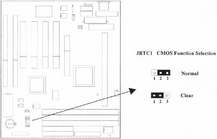
How to Clear the CMOS Setting
- Turn off the power.
- Remove power cable from power connector .
- Remove Yellow Jumper Cap from JRTC1(2-3)and put on JRTC1(1-2)to remove the CMOS setting.
- Remove Yellow Jumper Cap from JRTC1(1-2)and put on JRTC1(2-3).
- Connect power cable back to power connector .
- Turn on the power.
- While the system reboots, press <DEL> key to set the BIOS setup.
2.1.3 CPU Voltage Setting
The motherboard supports Pentium II VID function, the CPU core voltage is automatically detected, the range is from 1.3V to 3.5V.
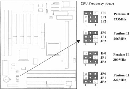
2.1.4 CPU Frequency Selection
| CPU Model | Ratio | JF0 | JF1 | JF2 |
| 233/66 | 3.5x | 1-2 | 2-3 | 2-3 |
| 266/66 | 4.0x | 2-3 | 1-2 | 1-2 |
| 300/66 | 4.5x | 2-3 | 1-2 | 2-3 |
| 333/66 | 5.0x | 2-3 | 2-3 | 1-2 |
2.2 Installation of CPU
The motherboard provides a Single Edge Contact(SEC)slot for a Pentium II processor packaged in an SEC cartridge. Follow these steps to install Pentium II CPU:
Mount the Universal Retention Mechanism (URM) & Insert the Pentium II CPU: ( The illustration is just for reference )
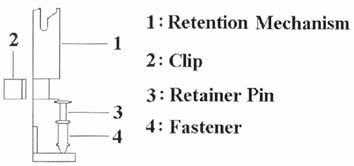
This URM was designed to accommodate 3 types of CPU Form Factor. ( SECC, SECCII & SEPP ). For Example : Pentium II & Celeron family.
�Note : Please put a soft pad under M/B before the installation of URM.
�Installation for SECC CPU :
- Leave space below each mounting hole for the fastener to protrude through the hole.
- Position URM on the M/B next to the slot1 connector.
- Push down retainer pin into respective fastener to secure URM onto the M/B.
- Push CPU into URM to contact with slot1.
- Make sure latching portion of CPU engaged with windows ledge of URM.
Installation for SECC II or SEPP CPU :
- Same as step (1) of SECC.
- Same as step (2) of SECC.
- Same as step (3) of SECC.
- Same as step (4) of SECC.
- Snap in 2 clips into side windows of URM to secure SEPP CPU.
If there is a fan on the CPU, Please plug in the fan cable to the three pin fan connector on the motherboard (CPUFAN).
2.3 Installation of Memory
P2LXB motherboard has 3x168-pin 64-bit Dual Inline Memory Module(DIMM)sockets divided into 3 banks. You can install 3.3V Extended Data Output(EDO)or Unbuffered Synchronous DRAM(SDRAM)memory. This will increase the system reliability.
2.3.1 Installation of 168-pin DIMM (Dual Inline Memory Module)
- Before inserting the DIMM, make sure the pin1 of the DIMM matches with the pin1 on the DIMM socket.
- Insert DIMM into the DIMM sockets at a 90-degree angle and press down.

2.3.2 Removal of 168-pin DIMM
- Press the holding clips on both sides of the socket outward to release the DIMM.
- Gently pull the DIMM out of the socket.
2.3.3 Memory Configuration
There is no jumper setting required for the memory size or type. It is automatically detected by the system BIOS, and the total memory size is to add them together.�
| DIMM Socket | DIMM Modules |
| DIMM1 | EDO/SDRAM 8, 16, 32, 64, 128MB |
| DIMM2 | EDO/SDRAM 8, 16, 32, 64, 128MB |
| DIMM3 | EDO/SDRAM 8, 16, 32, 64, 128MB |
2.4 I/O Connections/Panel Connections
I/O Connections
| ATXPWR | ATX Power Connector |
| ATPWR | AT Power Connector |
| CHASSISFAN | Chassis Fan Connector |
| CPUFAN | CPU Fan Connector |
| JIR1 | Infrared Connector (Cable optional)) |
| JWOL | Wake up on LAN connector |
| SB_LINK | For link with Creative's Sound7 Blaster 16 |
| JFLP1 | Floppy Disk Drive Connector |
| IDE1, 2 | Primary/ Secondary IDE Connectors |
| PS2 MOUSE | PS/2 Mouse Port |
| JKB1 | AT Keyboard Connector |
| JCOM1, 2 | Serial Ports 1 & 2 |
| JPRT1 | Printer Port |
| USB1, 2 | USB Connector |
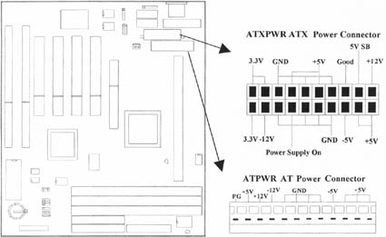
2.4.1 ATX Power Connector (20-pin ATXPWR), AT Power Connector (12-pin ATPWR)
Make sure that the power supply is off before connecting or disconnecting the power cable.
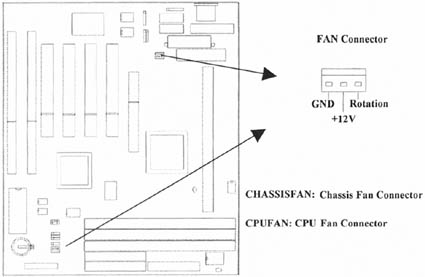
2.4.2 Chassis & CPU Fan Connectors (3-pin FAN)
Connect the fan's plug to the board taking into consideration the polarity of the connector.
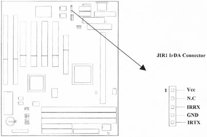
2.4.3 Infrared Connector (5-pin JIR1)
This connector supports the optional wireless transmitting and receiving infrared module, with this module and application software such as Laplink or Win95 Direct Cable Connection, user can transfer files to or from their laptops, notebooks, PDA, PCs and printers. The connector supports IrDA (115.2Kbps, 2 meters) and ASK-IR (56Kbps). Install infrared module onto Infrared connector and configure the setting through 'UART Mode Select'� in Integrated Peripherals to select whether UART is directed for use with COM2 or Infrared.
2.4.4 Wake-up on LAN Connector (3-pin JWOL)
The connector powers up the system when a wakeup packet or signal is received from the network . This feature requires the Wake up on LAN function in BIOS is set to Enabled and that your system has an ATX power supply with at least 720mA +5V standby power.
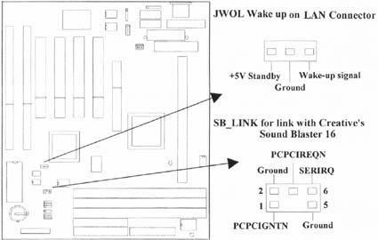
2.4.5 Creative��s SB_LINK Sound Connector (6-pin SB_LINK)
The SB_LINK serves as a bridge between the mainboard and Creative's PCI sound card. This connector delivers Sound Blaster 16 compatibility for real-mode DOS games.
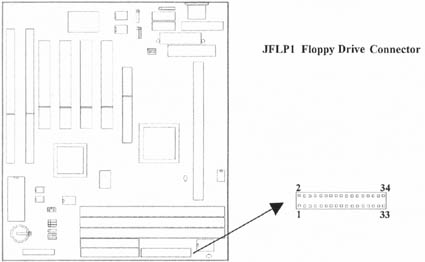
2.4.6 Floppy Disk Drive Connector (34-pin JFLP1)
This connector supports the provided floppy disk drive ribbon cable. Orient the red stripe to pin 1
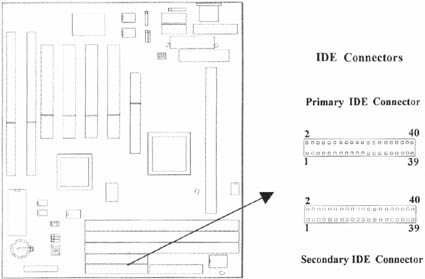
2.4.7 Primary/Secondary IDE Connector (Two 40-pin IDE)
These connectors support the provided IDE hard disk ribbon cable. Connect your first IDE hard disk to master mode of the primary channel. If you have second IDE device to install in your system, connect it as slave mode on the same channel, and the third and fourth device can be connected on secondary channel as master and slave mode respectively.
2.4.8 PS/2 Mouse Port (6-pin PS2 MOUSE1)
The system will direct IRQ12 to the PS/2 mouse.
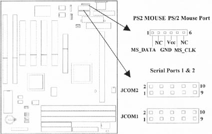
2.4.9 Serial Port (Two 10-pin COM)
2.4.10 Printer Port (25-pin JPRT1)
You can enable the parallel port and choose the IRQ through the ��Onboard Parallel Port�� setting in Integrated Peripherals of the COMS SETUP UTILITY.
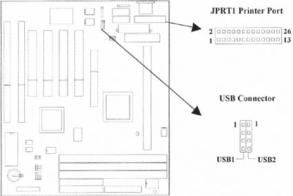
2.4.11 USB Connectors (Two 4-pin USB)
You can attach USB devices to the USB connector.
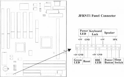
2.4.12 Panel Connection (24-pin JFRNT1)
| JFRNT1 Connector | Function |
| GREEN LED | Suspend Mode LED |
| PWR LED | Power LED |
| KEYLOCK | Keylock Switch |
| SPKR | Speaker |
| RESET | Reset Switch |
| IDE LED | HDD LED |
| PWR BTN | ATX Power Button Connector |
| SMI S/W | Sleep Switch |
WARNING: To avoid the system from failing, turn off the power before connecting any devices to the system.
Chapter 3. BIOS Setup
3.1 CMOS Setup Utility
To activate CMOS Setup, press <DEL> key immediately after you turn on the system. The following message "Press DEL to enter SETUP" should appear in the lower left hand corner of your screen.
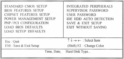
When you enter the CMOS Setup Utility, the Main Menu will be displayed (Figure 3-1). You can use arrow keys to select your function, press <Enter> key to accept the selection and enter the sub-menu.
- Figure 3-1. CMOS Setup Utility Main Screen
- ROM PCI/ISA BIOS (XXXXXXXX)
- CMOS SETUP UTILITY
- AWARD SOFTWARE, INC.
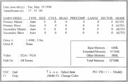
�3.2 Standard CMOS Setup
With the sub-menu (Figure 3-2), you can setup the; system date, system time, hard and floppy drive type, and display adapter type. Please refer to your equipment specification when changing the setup. Use arrow keys to highlight items, and use <PageUp>, <PageDown>, <+>, or <-> keys to scroll through the available options.
- Figure 3-2. Standard CMOS Setup Screen
- ROM PCI/ISA BIOS (XXXXXXXX)
- STANDARD CMOS SETUP
- AWARD SOFTWARE, INC.
3.2.1 Date
To assign the system date, the format is "mm.dd.yy". The input range for the Month is 1-12. Range for Date is 1-31. Range for Year is 1994-2079. System BIOS will calculate the day of the week automatically.
3.2.2 Time
To assign the system time, the format is "hh:mm:ss". The setting is in military time. When entering 2:34pm enter "14:34:00".
3.2.3 Hard Disks Setting
The BIOS supports Dual-Channel PIO and PCI Bus Master IDE ports. Each port supports one master and one slave hard drive. You can use <PageUp> or <PageDown> key to change hard drive type. Incorrect setting may result in boot up error or system hang.
If your hard disk drive is not listed, you can select Type "USER" to define your own drive manually. We recommend that you select Type "AUTO" for all drives. The BIOS will auto-detect the hard disk drive and CD-ROM drive at the POST stage.
If your hard disk drive is a SCSI device, please select "None" for your hard drive setting.
3.2.4 Floppy Drives A&B Setting
Select your floppy disk drive type. Options are 360KB(5.25"), 720KB(3.5"), 1.2MB(5.25"), 1.44MB(3.5"), 2.88MB(3.5").
3.2.5 Video Display Adapter Setting
Select the display adapter type for your system. Options are EGA/VGA, MONO, CGA40 and CGA80.
3.2.6 Halt On
This function allows the system to halt when an error is detected during Power-On Self-Test.
3.3 BIOS Features Setup
The sub-menu (Figure 3-3) includes all AWARD enhanced functions. The correct setting can enhance boot up efficiency. You can assign system speed, setup sequence, typematic and system password setting. You can enter <F1> key for help on highlighted topics. If you want to restore values before the changes you just made, press <F5> key. If you want to restore default value, press <F6> or <F7> key.
Figure 3-3. BIOS FEATURES SETUP SCREENROM PCI / ISA BIOS (XXXXXXXX)BIOS FEATURES SETUPAWARD SOFTWARE, INC.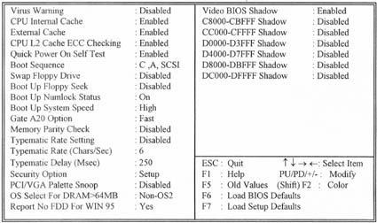
3.3.1 Virus Warning
When enabled, the BIOS will monitor the boot sector and the partition table on the hard drive for any attempt to modify. If an attempt is detected, the BIOS will halt the system and prompt the warning message. Select "Disabled" if you are installing a new operating system.
3.3.2 CPU Internal/External Cache
These options are to enable or disable CPU Internal (L1) Cache, or External (L2) Cache.
3.3.3 CPU L2 Cache ECC Checking
Select "Enabled" to enable CPU L2 Cache ECC Checking.
Select "Disabled" to disable CPU L2 Cache ECC Checking.
3.3.4 Quick Power On Self Test
Select "Enabled" to speed up time required to complete Power-On Self-Test.
3.3.5 Boot Sequence
This option allows user to assign boot sequence of the system. Available options are A, C, D, E, F, CD-ROM, SCSI and LS120/ZIP.
3.3.6 Swap Floppy Drive
When enabled, physical drive A will be assigned to logical drive B, and physical drive B will be assigned to logical drive A.
3.3.7 Boot Up Floppy Seek
The system will detect and verify operation of the floppy drive type .
3.3.8 Boot Up Numlock Status
The option allows the <NumLock> key to be activated after system boot up.
3.3.9 Boot Up System Speed
This option selects system boot up speed.
3.3.10 Typematic Rate Setting
Select "Enabled" to configure "Typematic Rate" and "Typematic Delay" functions.
3.3.11 Typematic Rate
Use this option to set the rate at which a character keeps repeating while you hold down a key.
3.3.12 Typematic Delay
Select "Enabled" to set the length of delay before key strokes to repeat. Available options are "250", "500", "750", and "1000".
3.3.13 Security Option
You can select whether the password is required every time the system boots or only when you enter the Setup. You can assign "Supervisor Password" and "User Password" in the main CMOS Setup Utility Screen.
3.3.14 PCI/VGA Palette Snoop
Enable this option to correct screen color shifts, when there is a combination of VGA cards, accelerator cards, or MPEG cards present.
3.3.15 OS Select for DRAM > 64MB
If you are using OS/2 operating system and installed memory is larger than 64MB. You need to have the setting in the enable mode.
3.3.16 Video BIOS Shadow
Video shadow copies BIOS code from slower ROM to faster RAM. BIOS can then execute from RAM.
3.3.17 C8000-CBFFF /DC000-DFFFF Shadow
Optional firmware will be copied from ROM to RAM. When this option is enabled.
3.4 Chipset Features Setup
These settings are intended for the Chipset function on the motherboard. Fine tuning these options, enhances the performance of the system.
Figure 3.4 CHIPSET FEATURES SETUP SCREEN ROM PCI / ISA BIOS (XXXXXXXX)CHIPSET FEATURES SETUPAWARD SOFTWARE, INC.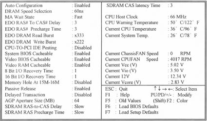
3.4.1 Auto Configuration
The optimum value for the chipset and CPU will be automatically loaded when enabled.
3.4.2 DRAM Speed Selection
This option must match the memory speed. If the installed memory is 60ns type, you should set it to "60".
3.4.3 EDO RAS# To CAS# Delay
These are timing of EDO CAS Latency and RAS to CAS Delay, calculated by clocks. They are important parameters affects EDO performance.
3.4.4 EDO RAS# Precharge Time
The RAS Recharge means the timing to inactive RAS and the timing for DRAM to do Recharge before next RAS can be issued.
3.4.5 System BIOS Cacheable
Allows the system BIOS to be cached for faster system performance.
3.4.6 Video BIOS Cacheable
Allows the video BIOS to be cached for faster video performance.
3.4.7 Video RAM Cacheable
This item lets you cache Video RAM A000 and B000.
3.4.8 8 Bit I/O Recovery Time
This option specifies the length of a delay inserted between consecutive 8-bit I/O operations.
3.4.9 16 Bit I/O Recovery Time
This option specifies the length of a delay inserted between consecutive 16-bit I/O operations.
3.4.10 Memory Hole At 15M-16M
Enabling this feature reserves 15MB to 16MB memory address space to ISA expansion cards that specifically require this setting. This makes the memory from 15MB and up unavailable to the system. Expansion cards can only access memory up to 16MB.
3.4.11 Passive Release
This function is used to meet the latency of the ISA bus master. Try to enable or disable it, if you have ISA card compatibility problem.
3.4.12 Delayed Transaction
This function is used to meet the latency of PCI cycles to from ISA bus. Try to enable or disable it, if you have ISA card compatibility problem.
3.4.13 AGP Aperture Size (MB)
Choose 4, 8, 16, 32, 64, 128, 256MB. Memory-mapped, graphics data structures can reside in the Graphics Aperture.
3.4.14 SDRAM RAS-to-CAS Delay
These are timing of SDRAM CAS Latency and RAS to CAS Delay, Calculated by clocks. They are important parameters affects SDRAM Performance.
3.4.15 SDRAM RAS Precharge Time
The RAS precharge means the timing to inactive RAS and the timing for DRAM to do precharge before next RAS can be issued.
3.4.16 CPU Host Clock
Default is 66 MHz. Choose 66, 75, 83MHz for the external frequency of your CPU.
The 75, 83MHz frequency are supported from PCB REV:1.01.
The frequency mapping table of the elements:
| Ext. frequency | AGP | PCI | ISA | DIMM |
| 66MHz | 66MHz | 33MHz | 8.33MHz | 66MHz |
| 75MHz | 75MHz | 37.5MHz | 8.33MHz | 75MHz |
| 83MHz | 83MHz | 41.6MHz | 8.33MHz | 83MHz |
Notice: The 75, 83 frequency are over specification.
Warning: Over specification operations are not recommended.
3.4.17 Current System & CPU Temperature (xx�XC/xx�XF)
The onboard hardware monitor is able to detect the temperatures of motherboard and CPU. These values refresh upon any key entry. The function is optional.
3.4.18 Current Chassis & CPU FAN Speed (xxxxRPM)
The onboard hardware monitor is able to detect the chassis fan speed and CPU fan speed in Rotations Per Minute (RPM). These values refresh upon any key entry in the BIOS setup screen. The function is optional.
3.4.19 Vcc, Vio, 12V, Vcore (xx.xxV)
The onboard hardware monitor is able to detect the voltage output by the voltage regulators. These values refresh upon any key entry. The function is optional.
3.5 Power Management Setup
Power management decreases power usage under the pre-defined standby time range.
Figure 3-5. POWER MANAGEMENT SETUP SCREENROM PCI / ISA BIOS (XXXXXXXX)POWER MANAGEMENT SETUPAWARD SOFTWARE, INC.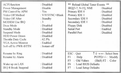
3.5.1 ACPI Function
This item allows you to enable or disable the function of Advanced Configuration and Power Interface which offers improved power management .
3.5.2 Power Management
| Disable | Disable Power Management. |
| Mini Saving | System starts power saving function when the inactivity period exceeds 1 hour. |
| Max Saving | System starts power saving function when the inactivity period exceeds 1 min. |
| User Defined | Allows user to define the inactivity period before power saving function activates, |
3.5.3 PM Control by APM
Select "Yes" if your system has Advanced Power Management (APM).
3.5.4 Video Off Method
This field defines the video off features. The following options are available: DPMS OFF, DPMS Reduce ON, Blank Screen, V/H SYNC+Blank, DPMS Standby, and DPMS Suspend. The DPMS (Display Power Management System) features allow the BIOS to control the video display card if it supports the DPMS feature.
3.5.5 Video Off After
This option allows your monitor to blank after your system went into Doze, Standby or Suspend mode. You can elect to not blank screen by select N/A. Default value is "Standby".
3.5.6 Doze Mode
When system is inactive after the predefined time limit, system performance will drop down. This is the first level of Power Management.
3.5.7 Standby Mode
System turns off the video signal and the fixed drives. This is the second level of Power Management.
3.5.8 Suspend Mode
System further shuts down all devices except for CPU itself. This is the third level of Power Management.
3.5.9 HDD Power Down
This instructs hard drives to shut off while in the Power Management modes.
3.5.10 VGA Active Monitor
To enable or disable the detection of VGA activity for power down state transition.
3.5.11 Soft-off by PWR-BTTN ( for ATX power supply )
When set to Delay 4 Sec., the ATX switch can be used as a normal system power-off button when pressed for less than 4 seconds. Instant disables the ATX switch function when the button is pressed under 4 seconds.
3.5.12 Resume by Ring ( for ATX power supply )
This option lets you specify enable or disable external Modem Wake Up function. The function of power on through modem when system is off.
To select Enabled : To let the system to enter the environment of DOS or Windows 95/98 OS before system is power off. As long as there are any massage through the Modem to enter the System during system is power off. The system will enable power on function.
3.5.13 Resume by Alarm ( for ATX power supply )
Set this option to enable or disable the RTC Alarm to Wake Up the system which is set at soft Off.
3.5.14 Wake up on LAN ( for ATX power supply )
This allows you to remotely power up your system through your network by sending a wake-up frame or signal. With this feature, you can remotely upload/download data to/from systems during off-peak hours. Set to Enabled to set this feature.
3.5.15 Date (of Month) Alarm, Time (hh:mm:ss) Alarm
Set these options to specify the RTC Alarm time on Date / Hour / Minute / Second.
3.5.16 IRQ 8 Break Suspend
To enable or disable the detection of IRQ 8 (RTC) event for power down state transition.
3.5.17 IRQ[3-7, 9-15], NMI
To enable or disable the detection of IRQ 3-7, IRQ 9-15 or NMI interrupt events for power down state transition.
3.5.18 Primary/Secondary IDE 0/1, Floppy Disk, Serial & Parallel Port
These items enable or disable the detection of IDE, floppy, serial and parallel port activities for power down state transition. Actually it detects the read/write to/from I/O port.
3.6 PNP/PCI Configuration Setup
Figure 3.6 PNP/PCI CONFIGURATION SETUPROM PCI / ISA BIOS (XXXXXXXX)PNP/PCI CONFIGURATIONAWARD SOFTWARE, INC.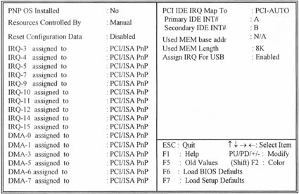
�
3.6.1 PNP OS Installed
This field allows you to use a Plug-and-Play (PnP) operating system.
Please set it as� No� if the operating system has no PnP function or to avoid reassigning the IRQs by the operating system.
3.6.2 Resources Controlled By
Default setting is "Auto". This setting allows the BIOS to self detect setting and Plug-and-Play devices during start up. The user can select and configure IRQs under "Manual" mode.
3.6.3 Reset Configuration Data
In case a conflict occurs after you assign the IRQs or after you configure your system, you can enable this function to allow your system to automatically reset your configuration and reassign the IRQs, DMAs, and I/O address.
3.6.4 IRQ-xx assigned to
If your ISA card is not PnP compatible and requires a special IRQ to support its function, set the selected IRQ-x assigned to :Legacy ISA. This setting informs the PnP BIOS to reserve the selected IRQ for the installed legacy ISA card.
3.6.5 DMA-x assigned to
If your ISA card is not PnP compatible and requires a special DMA channel to support its function, set the selected DMA channel to Legacy ISA. This setting informs the PnP BIOS to reserve the selected DMA channel for the installed legacy ISA card.
3.6.6 PCI IDE IRQ Map To
Some old PCI IDE add-on cards are not fully PnP compatible. These cards require you to specify the slot in use to allow the BIOS to properly configure the PnP resources.
3.6.7 Primary/Secondary IDE INT#
These two items, in conjunction with item PCI IDE IRQ Map To, specify the IRQ routing of the primary or secondary channel of the PCI IDE add-on card.
3.6.8 Used MEM base addr
This item, in conjunction with the ��Used MEM Length��, lets you set a memory space for non-PnP compatible ISA card.
3.6.9 Assign IRQ For USB
Default is Enabled. You can disable this item when you do not attach any USB devices on board and need extra IRQ for other device. The yellow exclamation mark will be shown in System/Device Manager under Windows 95/98 if you disable this item. This is a normal status.
3.7 Integrated Peripherals
You can control Input and Output functions from this screen.
Figure 3-7 Integrated PeripheralsROM PCI / ISA BIOS (XXXXXXXX)INTEGRATED PERIPHERALSAWARD SOFTWARE, INC.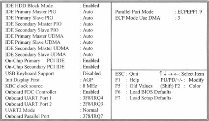
�
3.7.1 IDE HDD Block Mode
This feature enhances disk performance by allowing multi-sector data transfers and eliminates the interrupt handling time for each sector.
3.7.2 IDE Primary & Secondary Master/Slave PIO
These four PIO fields let you set a PIO mode (0-4) for each of four IDE devices. When under "Auto" mode, the system automatically set the best mode for each device
3.7.3 IDE Primary & Secondary Master/Slave UDMA
When set to "Auto" mode, the system will detect if the hard drive supports Ultra DMA mode.
3.7.4 On-Chip primary/Secondary PCI IDE
Select "Enabled" to activate each on-board IDE channel separately, Select "Disabled", if you install an add-on IDE Control card
3.7.5 USB Keyboard Support
This item lets you enable or disable the USB keyboard driver within the onboard BIOS.
3.7.6 Init Display First
This item lets the system to detect AGP or PCI-Slot first when boot-up.
3.7.7 Onboard FDC Controller
Select "Enabled" to activate the on-board FDC
Select "Disabled" to activate an add-on FDC
3.7.8 Onboard UART Port 1 & 2
Select an address and corresponding interrupt for the first/second serial port. The default value for the first serial port is "3F8/IRQ4" and the second serial port is "2F8/IRQ3".
3.7.9 UART2 Mode
Select to activate the Infrared transfer function.
3.7.10 Onboard Parallel Port
Select address and interrupt for the Parallel port.
3.7.11 Parallel Port Mode
Select an operating mode for the parallel port. Mode options are SPP, EPP1.7, ECPEPP1.7, EPP1.9, ECP and ECPEPP1.9.
3.7.12 ECP Mode Use DMA
Select a DMA channel if parallel port is set as "ECP" , "ECPEPP1.7" or�� ECPEPP1.9 ��.
3.8 Load BIOS Defaults
This loads the standard BIOS default values. To select, highlight it and press the <Enter> key. Then press the <Y> and <Enter> keys to confirm. Otherwise, press the <N> key to cancel.
3.9 Load Setup Defaults
This feature loads the setup default values from BIOS default table. To select, highlight it and press the <nter> key. Then press the <Y> and <Enter> keys to confirm. Otherwise, press the <N> key to cancel.
3.10 Supervisor/User Password
You can assign, modify, or cancel password settings. To modify, highlight "Supervisor Password" or "User Password" and press the <Enter> key. The screen will prompt you ("Enter Password:"). Enter your password. The maximum size of the password is 8 characters. System will prompt you to reenter the password to verify. Remember the passwords are case sensitive.
If you want to remove the passwords, either delete passwords or press <Enter> when prompting for new password.
If you want it to require password upon initial system startup and upon entering the CMOS Setup Utility, you will need to change the selection of the (Security Option) under (BIOS FEATURES SETUP) to "System".
If the setting is "Setup", the system will only require the password you activate CMOS Setup Utility.
3.11 IDE HDD Auto Detection
If your system has an IDE hard drive, you can use this function to detect its parameters and enter them into the Standard CMOS Setup automatically.
This routine only detects one set of parameters. If your hard disk is formatted using different parameters than those detected, you have to enter the parameters manually. If the parameters listed do not match the ones used to format the disk, the information on that disk will not be accessible. If the auto-detected parameters displayed do not match those that are used for your drive, ignore them. Type N to reject the values and enter the correct ones manually from the Standard CMOS Setup screen.
3.12 Exit CMOS Setup Utility
Press the <F10> key to save the setup and exit. Press <ESC> key to exit without saving. Either saving or not saving modifications, screen will prompt user to confirm, and system will reboot on exit.